Golf Mk3
|
Servicing heating system
Servicing heating system
|
 |
|
|
Warning!
Always disconnect the battery earth strap before working on the electrical system. Note: Before disconnecting battery, obtain radio code for radios with anti-theft coding.
|
|
|
|
|
|
|
|
|
|
|
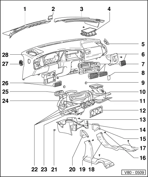
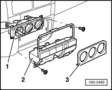
=> General body repairs; Repair Group 70; Removing and installing dash panel
|
|
|
=> General body repairs; Repair Group 70; Removing and installing dash panel |
 |
|
|
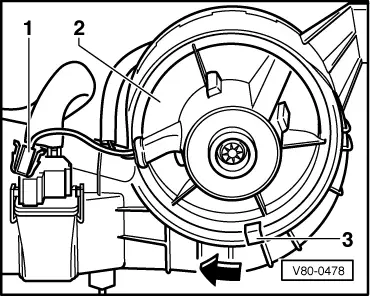
→ Fig.2 Removing fresh air blower -V2-
|
 |
|
|
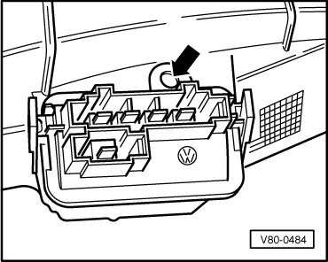
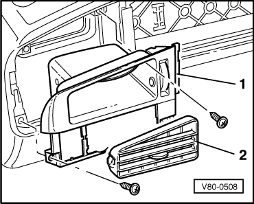
→ Fig.4 Removing and installing vent
|
 |
|
|
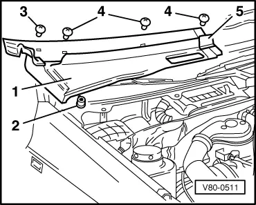
→ Fig.5 Removing and installing right-hand side plenum chamber cover
|
 |
|
|
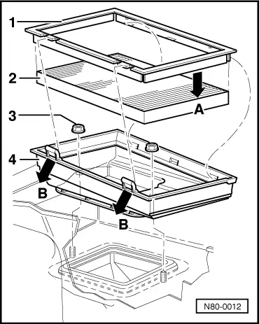
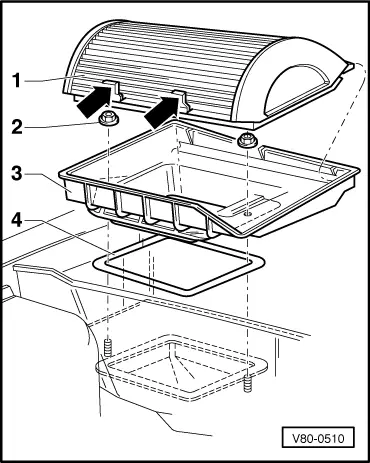
→ Fig.6 Removing and installing dust and pollen filter (vehicles up to vehicle identity No. 1H-P-990 000)
Note: If the filter element is to be changed then additionally remove the housing and install the dust and pollen filter for vehicles from vehicle identity No. 1H-R-000 001 (=> Fig.7 ). |