
Golf Mk3
|
Servicing power assisted steering
Dismantling and assembling power assisted steering box (TRW)
|
 |
|
|
Dismantling
|
 |
|
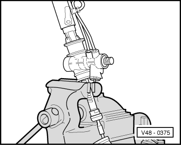
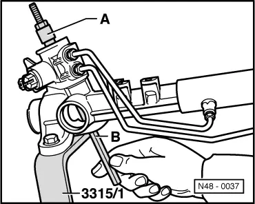
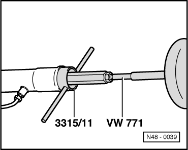
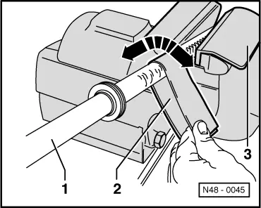
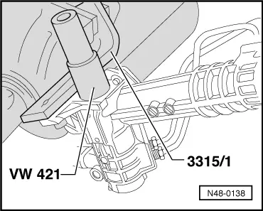
Note: Use vice clamps, check vice clamps for impurities e.g. metal filings or similar and thoroughly remove. If a spanner face is present on the rack then use an open jaw spanner to counter hold. The rack should not then be tensioned in a vice. |
 |
|
 |
|
Notes:
|
 |
|
|
 |
|
|
 |
|
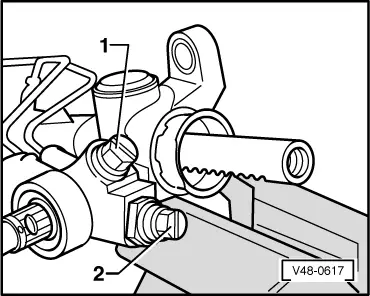
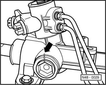
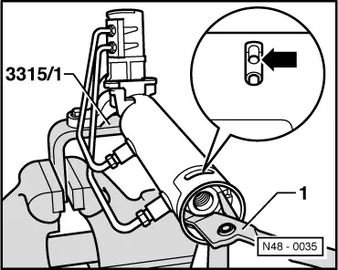
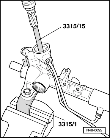
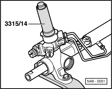
If it is very tight, loosen plug with a hammer and drift. |
 |
|
|
 |
|
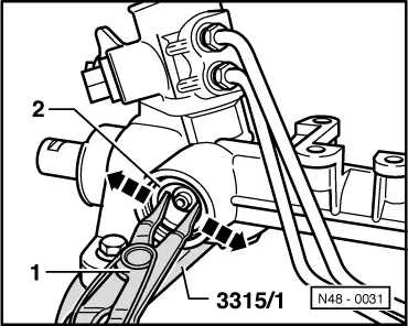
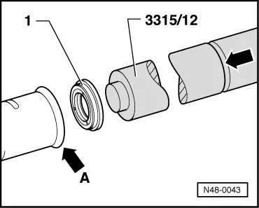
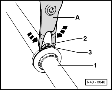
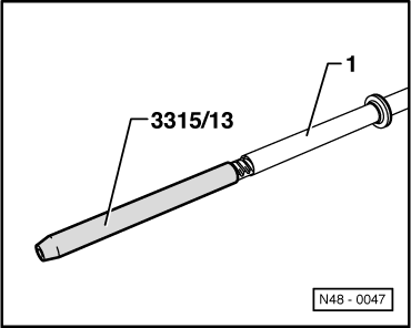
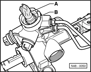
When inserting the puller -A- ensure that the claws (arrow on illustration Page 48-61) locate properly under the oil seal. The puller must not be spread too far, otherwise the oil seal seating in the housing will be damaged or the oil seal can jam in the housing. |
 |
|
Assembling Before assembling the housing must be checked for impurities (paint residue, metal particles, dirt) and thoroughly cleaned if necessary. Notes:
|
 |
|
|
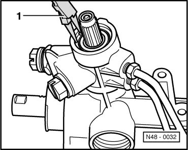
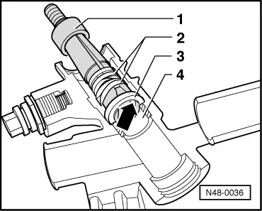
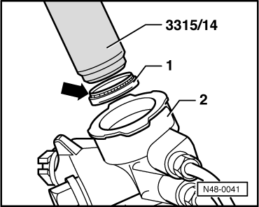
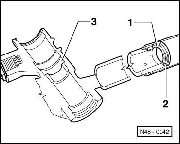
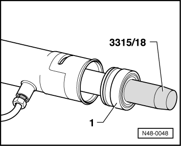
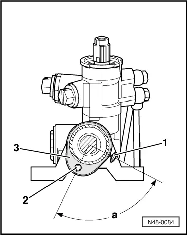
Installation position for valve body oil seal → The oil seal sealing lip (arrow) faces upwards. For ease of illustration Fig. shows valve turret sectionalised. Installing rack inner oil seal |
 |
|
 |
|
|
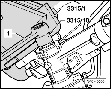
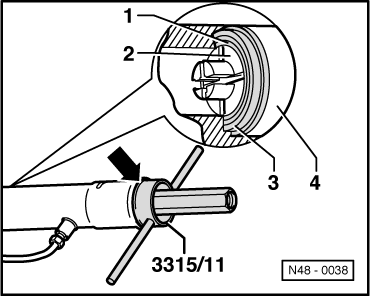
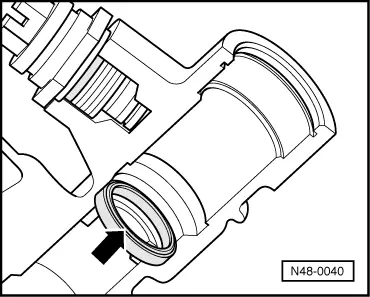
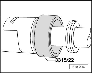
→ Installation position for rack oil seal The oil seal support ring faces to valve body housing
For ease of illustration the illustration shows the housing sectionalised. |
 |
|
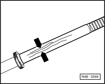
If the old rack is to be used again, check the seal for scoring. If scoring is visible or perceptible the seal and O-ring underneathed must be replaced. |
 |
|
Renewing rack seal
|
 |
|
No grease must be allowed to get into the oil circuit!
|
 |
|
When sliding in ensure that the seal is pressed into the groove in the piston without jamming.
|
 |
|
|
 |
|
Ball bearing must not be canted when driving in |
 |
|
Ensure that the seal in housing is not damaged by the rack teeth! |
 |
|
|
 |
|
|
|
|
Notes: |
 |
|
If the rack has been replaced then adjust steering box before assembling track rods as described on Page 48-75. Install ball joints |
|
|
Note: Use vice clamps, check vice clamps for impurities e.g. metal filings or similar and thoroughly remove. |
 |
|
|
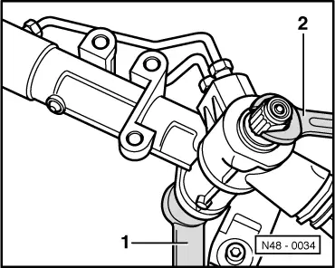
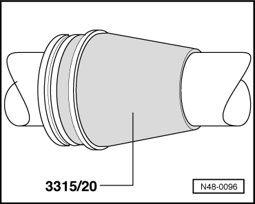
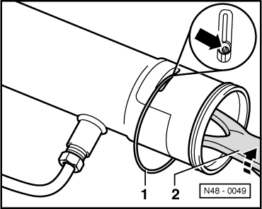
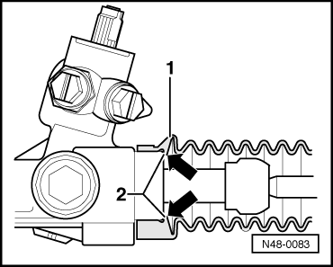
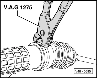
→ Bellows installation position
When installing the bellows ensure that the lip (arrows) lies against the housing |
 |
|
|
→ Clamp installation position
|
 |
|