volkswagen Workshop Repair Guides

Volkswagen Workshop Service and Repair Manuals

Adjusting bevel gear > < Recommended sequence for adjusting gear set
5 Speed Manual Gearbox 02C four wheel drive
Adjusting bevel gear and shaft bevel gear (gear set)
Adjusting shaft bevel gear

Adjustment of the shaft bevel gear is required when

  • ◆ Bevel gear housing
  • ◆ Shaft bevel gear taper roller bearings

or the

  • ◆ Gear set

are replaced.

Adjustment overview

Determining thickness of shim "S3"

  • ‒ Press shaft bevel gear large taper roller bearing outer race without shim into bevel gear housing with press piece 2050.
  • ‒ Press shaft bevel gear small taper roller bearing outer race into bevel gear housing with tube VW 415 a.
  • ‒ Press large taper roller bearing inner race onto shaft bevel gear with tube VW 415 a.
  • ‒ Insert shaft bevel gear.
  • ‒ Heat small taper roller bearing inner race to approx. 100 °C and fit onto shaft bevel gear without spacer sleeve and lightly press home using tube 2040.
 
V39-0822
  • ‒ Counter hold shaft bevel gear hexagon nut with socket 3156, measure friction torque and increase tightening torque until the prescribed friction torque is achieved => Page 39-133 .
  • ‒ → Set adjustment ring of universal mandrel VW 385/1 to dimension "a" = 75 mm.
  • ‒ Set sliding adjustment ring to dimension "b" = 95 mm.
 
V39-1027
  • ‒ → Assemble universal mandrel as shown in illustration. Measuring gauge extension VW 385/20 = 3 mm. Set universal gauge VW 385/30 to Ro = 34.70 mm.
  • ‒ Preload dial gauge to 3 mm and zero.
 
V39-1028
  • ‒ → Screw in ring nut with new O-ring by hand until the O-ring provides a play free seating for the ring nut.

Note:

Fit ring nut without drive flange seal.

 
V39-1031
  • ‒ → Position end-measuring plate on head of shaft bevel gear.
 
V39-1032
  • ‒ → Insert universal mandrel.
  • ‒ Fit rear axle housing with ball bearing installed. To do this first guide sleeve 385/35 into bearing then press rear axle housing onto lower dowel sleeve, finally press rear axle housing onto upper dowel sleeve.
  • ‒ Tighten hexagon bolts to torque setting.
  • ‒ Using sliding setting ring, pull sleeve 385/35 outwards until the mandrel can just be turned by hand.
 
V39-1033
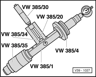
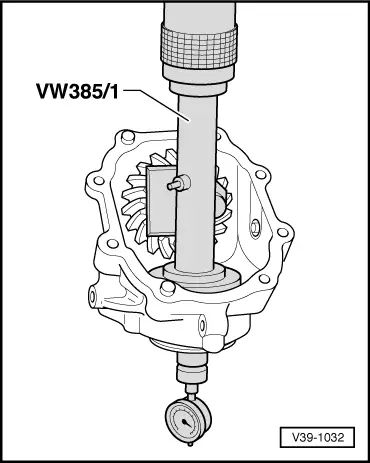
  • ‒ → Measure dimension "e".
    Turn mandrel until tip of dial gauge makes contact with end measuring plate and indicates max. deflection (return point). The measured value is dimension "e" (red number range). Example: 1.17 mm.
  • ‒ Remove universal mandrel.

Note:

Finally, check again whether dial gauge with master gauge VW 385/30 in position and with 3 mm preload points to "0", otherwise repeat measurement.

Determining shim thickness "S3"

S3 = e - r

e

-

Determined value (max. deflection)

r

-

Deviation (on bevel gear given in 1/100 mm)

Example:

Measured dial gauge value "e"

1.17 mm

Deviation inscribed on bevel gear "r"

- 0.32 mm

Shim thickness "S3"

= 0.85 mm

The following adjustment shims are available:

Size (mm)

Part No.

0.15
0.30
0.35
0.40
0.50

009 409 247
009 409 247A
009 409 247B
009 409 247C
009 409 247D

  • ‒ Remove shaft bevel gear and install again with determined shim S3 and distance sleeve.
  • ‒ Tighten hexagon nut as described on Page 39-132 .

Checking dimension "r"

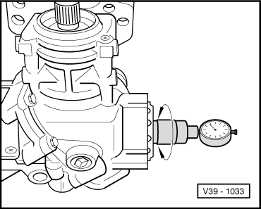
  • ‒ Rotate shaft bevel gear several times in both directions.
  • ‒ Insert universal mandrel and carry out check measurement.

If correct shims have been selected, the dial gauge reading anti-clockwise (red number range) must indicate the value of the inscribed deviation "r" on bevel gear with a tolerance of + 0.04 mm.

Adjusting bevel gear > < Recommended sequence for adjusting gear set