|
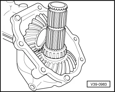
Shaft bevel gear with shim S3 installed.
Bevel gear with a 1.2 mm thick shim installed on the S2 side.
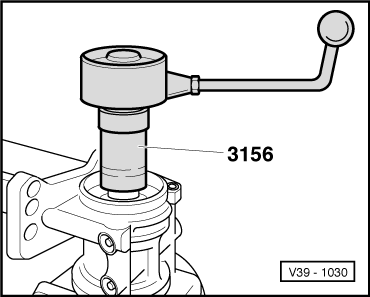
Total friction torque set.
-
‒ →
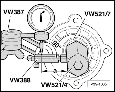
Assemble measuring tools.
-
‒ Dial gauge extension approx. 25 mm long.
-
‒ Dimension "a" = 39 mm.
-
‒ Screw measuring lever VW 388 in so that the dial gauge extension is at right angles to the measuring surface.
-
‒ Turn bevel gear on to stop. Set dial gauge to zero, turn bevel gear back and measure play. Note value.
-
‒ Loosen clamping sleeve locking screw and, after turning bevel gear through a further 90°repeat complete measuring process a further three times. Add the four measured values together and calculate average backlash.
Calculating average backlash
Example:
|
|
1st measurement
|
0.45 mm
|
|
|
+
|
2nd measurement
|
0.44 mm
|
|
|
+
|
3rd measurement
|
0.45 mm
|
|
|
+
|
4th measurement
|
0.46 mm
|
|
|
Total
|
1.80 mm
|
|
|
|
|
|
|
Average backlash = 1.80 mm /4
= 0.45 mm.
Note:
The relationship backlash to bevel gear with input shaft displacement is almost a ratio of 1:1. Therefore the calculated average backlash can be used directly for calculating S2.
Determining shim S2 thickness
|
S2
|
=
|
Inserted shim
|
|
|
-
|
average backlash
|
|
|
+
|
Lift (constant value)
|
Lift = 0.20 mm
|
Example:
|
|
|
|
Fitted shim
|
1.20 mm
|
|
-
|
average backlash
|
0.45 mm
|
|
|
|
0.75 mm
|
|
+
|
Lift (constant)
|
0.20 mm
|
|
S2
|
=
|
0.95 mm
|
The following adjustment shims are available:
|
|
|---|
|
Size (mm)
|
Part No.
|
|
0.15
0.20
0.30
|
113 517 201A
113 517 202A
113 517 203A
|
|
0.40
0.50
0.60
|
113 517 204A
113 517 205A
113 517 206A
|
|
0.70
0.80
0.90
|
113 517 207A
113 517 208A
113 517 209A
|
|
1.00
1.20
|
113 517 210A
113 517 211A
|
-
‒ Remove rear axle housing, remove bearing support and press taper roller bearing outer race out. Remove 1.2 mm shim.
-
‒ Insert determined S2 and reinstall outer race.
Carrying out check measurement
-
‒ Install rear axle housing with installed bearing support to bevel gear housing.
-
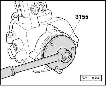
‒ Tighten ring nut until the total friction torque is set.
-
‒ Measure backlash, it must be between
0.15 - 0.25 mm.
-
‒ Mark position of ring nut to housing.
After installing components and after installing rear axle housing to bevel gear housing tighten ring nut to the position marked during control measurement.
|