volkswagen Workshop Repair Guides

Volkswagen Workshop Service and Repair Manuals

Servicing gearbox housing and clutch housing > < Removing and installing input shaft, output shaft (pinion shaft), differential and selector forks
5 Speed Manual Gearbox 02C four wheel drive
Dismantling and assembling gearbox
Dismantling and assembling sequence

Dismantling and assembling gearbox housing cover, gearbox housing, selector mechanism, input shaft, output shaft (pinion shaft), differential and selector forks

Dismantling

  • ‒ Drain gearbox oil.

On vehicles with 6 cylinder injection engine:

 
N34-0098

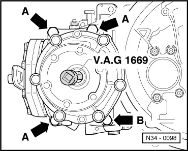
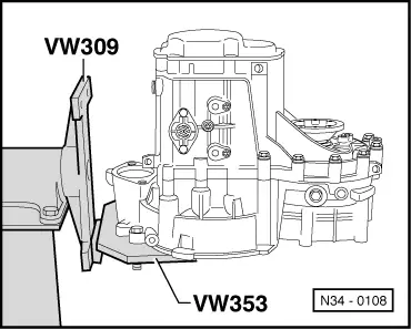
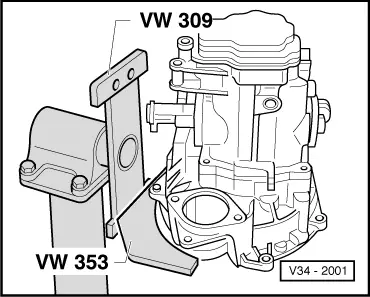
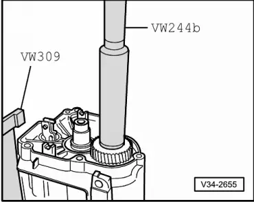
Remove bevel box as follows:

  • ‒ Remove cap by piercing cap centre with a screwdriver and levering out.
  • ‒ → Remove drive flange counter sunk head bolt with V.A.G 1669 or 6 mm socket insert cone (commercially available) and counter hold against turning with a drift.
  • ‒ Pull drive shaft with drive flange out carefully and note spring behind drive flange.
  • ‒ Remove bevel box/gearbox connecting bolts (arrows -A- and -B-).
  • ‒ Press bevel box off gearbox.
 
N34-0108

On vehicles with 6 cylinder injection engine:

  • ‒ → Secure gearbox in assembly stand.

On vehicles with 4 cylinder engine:

 
V34-2001
  • ‒ → Secure gearbox in assembly stand.
 
V34-2611
  • ‒ Remove clutch release lever and release bearing .
  • ‒ Remove guide sleeve => Page 30-15 .
  • ‒ → Remove gearbox housing cover (arrow).
 
V34-2612
  • ‒ → Remove 5th gear selector fork (arrow)

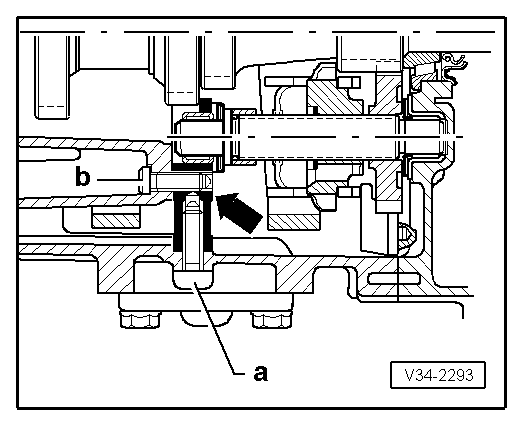
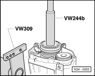
Note:

Before lifting the locking collar, take off spring and lock body. Then afterwards replace locking collar on syncro-hub again, but without selector fork.

 
V34-2613
  • ‒ → Remove bolts -A- for synchro-hub and 5th gear, to do this select 1st gear (arrows 2 and 3) and 5th gear (arrow 1).
  • ‒ After engaging both gears the input shaft and output shaft are locked, synchro-hub and gear wheel cannot turn. Both bolts can now be loosened.
 
V34-2312
  • ‒ → Pull off synchro-hub with 5th gear wheel and take off needle roller bearing.
  • A - Two arm puller e.g. Kukko 20/10 with Matra V/170 hooks.
  • B - Hexagon bolt M10 x 20
 
V34-2313
  • ‒ → Pull off 5th gear wheel
  • A - Two arm puller e.g. Kukko 20/10 with Matra V/170 hooks.
  • B - Hexagon bolt M10 x 20
  • Removal sequence:
    • ‒ Assemble two arm puller and centralize by turning screw (arrow).
    • ‒ Pull gear wheel off with two arm puller, first heat with hot air blower V.A.G 1416 if necessary.

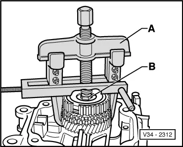
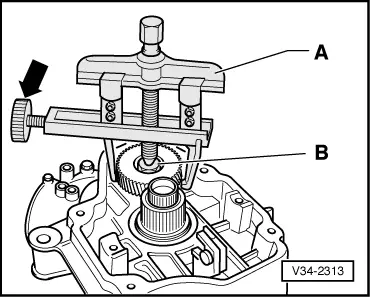
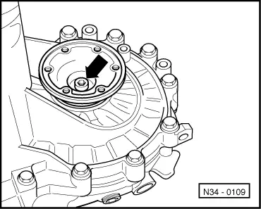
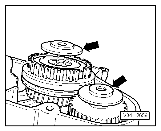
Note:

When pulling off the gear wheel ensure that the hooks do not bend outwards, if necessary tighten screw (arrow). Check 5th gear wheel for damage after removal.

 
N34-0109
  • ‒ → Remove left-hand flange shaft, to do this remove counter sunk head bolt (arrow).
 
V34-2007
  • ‒ → Remove both reverse shaft support bracket bolts (arrows).
 
V34-2016
  • ‒ → Remove selector shaft with selector cover, to do this place selector shaft in neutral position. Then remove bolts (arrows) and pull selector shaft out of the gearbox housing.
 
N34-0110
  • ‒ → Remove cover plate -A- and pivot pins -B- from underside of gearbox.
 
V34-2615
  • ‒ → Remove pivot pins -A- on top side of gearbox and gearbox housing to clutch housing securing bolts -B- in area of differential.
 
N34-0111
  • ‒ → Remove bolts -A-, from inside clutch housing for securing clutch housing to gearbox housing.

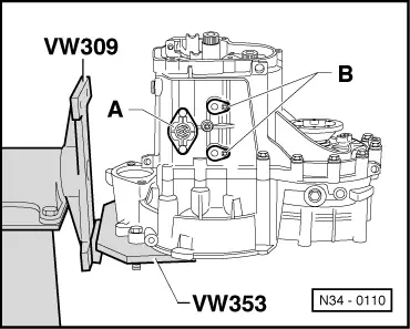
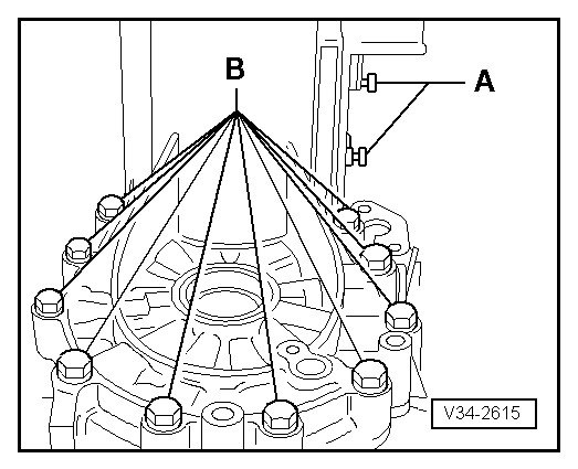
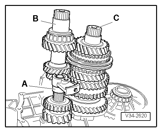
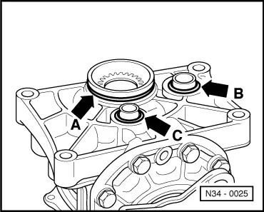
Note:

Do not remove nuts -B- for output shaft bearing support.

 
V34-2618
  • ‒ → Take-off gearbox housing, if necessary carefully lever up all round and alternating between sides on the protruding housing flange (arrows), being careful not to damage sealing surfaces.
 
V34-2619
  • ‒ → Remove selector forks -A- together with selector plates.
  • ‒ Unscrew bolt for selector mechanism for reverse gear -B-.
 
V34-2620
  • ‒ Remove nuts for output shaft bearing support (=> Page 34-96 , illustration N34-0111, item -B-).
  • ‒ → Remove reverse gear -A-, input shaft -B- and output shaft -C- one after the other from clutch housing.
  • ‒ Take out differential.

Assembling

  • ‒ Install differential.
 
V34-2653
  • ‒ → Always renew sealing rings (arrows) for output shaft bearing support.

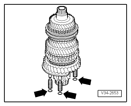
Note:

The illustration only shows 3 of the 4 sealing rings.

  • ‒ Install input shaft, output shaft and reverse shaft together.
  • ‒ Tighten nuts for output shaft bearing support.
  • ‒ Clean locking fluid remnants from threads in the reverse shaft support (=> Page 34-100 , illustration V34-2293, arrow). The remnants can be removed using a tap.
 
V34-2012
  • ‒ Install reverse shaft support.
  • ‒ Install reverse gear selector mechanism.

→ Installation position reverse gear

  • ‒ Install selector forks together with selector plates.
 
V34-2008
  • ‒ → Screw M 8 x 100 mm studs -A- into reverse shaft support so that the shaft is aligned after fitting gearbox housing.
  • ‒ Align selector plates.

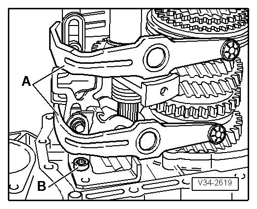
Note:

The selector segments must be positioned in the grooves on the locking collars.

  • ‒ Fit gearbox housing.
 
V34-2293

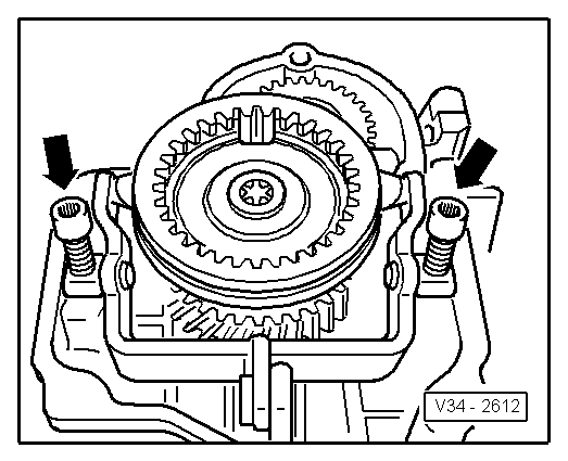
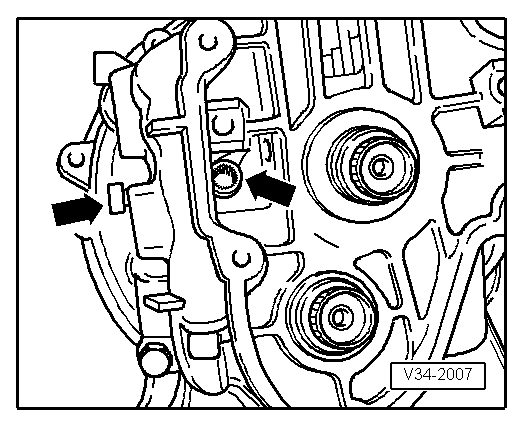
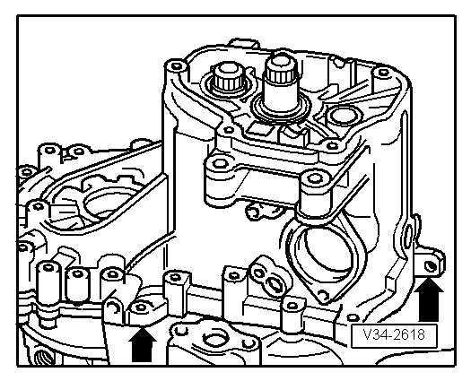
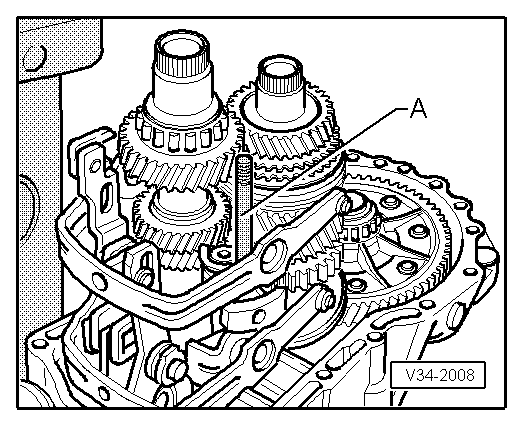
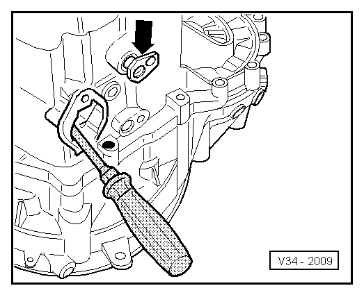
Install reverse shaft support bolts (arrow) as follows:

  • ‒ → Insert bolt -a-, remove stud (=> Illustration V34-2008), insert bolt -b- and hand tighten.
  • Tightening sequence:
  • 1 - Bolt -a- 30 Nm
    2 - Bolt -b- 30 Nm
 
V34-2009
  • ‒ → Install pivot pin (arrow) for selector forks. To do this align selector mechanism with a screwdriver, so that the relevant pivot pin can be installed.
  • ‒ Fit selector shaft cover
 
V34-2006

→ Install selector shaft as follows:

  • ‒ Place selector plates in neutral.
  • ‒ Locate lug (arrow 1) in the recess in gearbox housing. Position selector shaft so that selector finger (arrow 2) is inserted in the selector plates.
  • ‒ Install selector shaft cover.
 
V34-2654

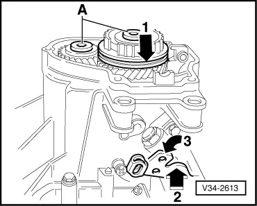
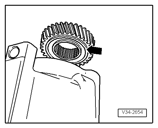
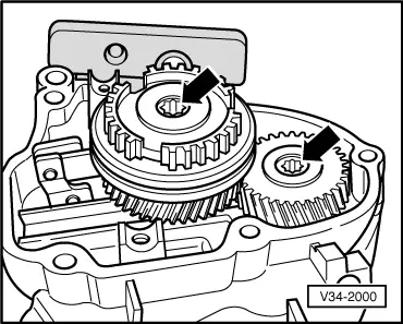
→ Installation position 5th gear wheel

The circumferential groove (arrow) faces to gearbox housing.

 
V34-2655
  • ‒ → Knock-on 5th gear wheel.
 
V35-1125

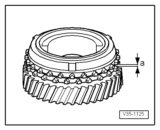
Checking 5th gear synchro-ring

  • ‒ → Before installing 5th gear wheel and synchro-ring press the synchro-ring onto the cone of the gear wheel and measure gap -a- with a feeler gauge.

Gap -a-

New

Wear limit

5th gear

1.1 ... 1.7 mm

0.5 mm

  • ‒ Install 5th gear wheel with needle roller bearing
  • ‒ Place 5th gear synchro-ring on gear wheel
  • ‒ Assembly 5th gear synchro-hub/locking collar before installing => Page 35-12 .
 
N34-0059

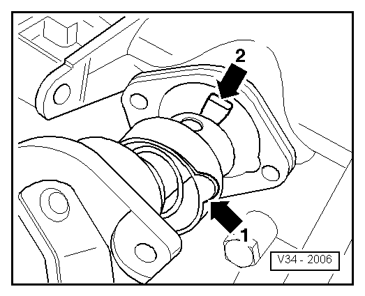
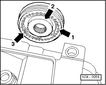
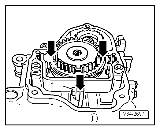
→ Installation position 5th gear synchro-hub/locking collar

The pointed teeth of the locking collar (arrow 1) and the high shoulder of the synchro-hub (arrow 2) face the gearbox housing.

The syncro-hub mountings (arrow 3) align with the synchro-ring cast locking pieces (=>arrows on Illustration N35-0018, Page 34-104 ).

 
N35-0018

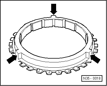
→ 5th gear synchro-ring with cast locking pieces (arrows)

 
N34-0053
  • ‒ → Knock-on 5th gear synchro-hub

Note:

When driving on ensure synchro-ring is free to move.

 
V34-2658
  • ‒ Screw-in securing bolts for synchro-hub and 5th gear wheel.

→ Installation position of dished spring for gear wheel and 5th gear synchro-hub securing bolts:

The outer diameter (concave side -arrows-) faces 5th gear.

 
V34-2000
  • ‒ → Engage two gears before tightening 5th gear synchro-hub and gear wheel securing bolts (arrows) (=>Illustration 34-2613, Page 34-92 )
  • ‒ Install 5th gear selector fork.
 
V34-2697

→ Adjusting 5th gear:

  • ‒ Engage 5th gear. Loosen bolt -1-. Press locking collar and selector fork jaws in direction of arrow, then tighten bolt -1- to 25 Nm.
  • ● Check measurement :
    It must not be possible to slide a 0.2 mm feeler gauge between locking collar and gear wheel. If necessary repeat adjustment.
  • ‒ Disengage 5th gear. Locking collar must now be in the neutral position. Synchro-ring must move freely.
  • ‒ Fit gearbox housing cover
  • ‒ Install flange shaft complete => Page 34-85
  • ‒ Remove gearbox from assembly stand and place down.

On vehicles with 6 cylinder injection engine:

 
N34-0025

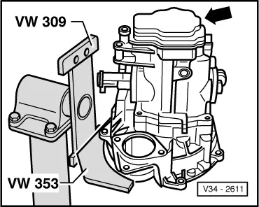
Build bevel box on as follows:

  • ‒ → Always replace sealing ring to seal bevel box/gearbox (arrow A) and sealing rings to seals sleeves for the oil supply system (arrow B and C), lightly coat with oil.
  • ‒ Push bevel box completely onto gearbox, thereby ensuring that the bevel box input shaft teeth are guided centrally onto the differential connecting piece.
  • ‒ If the teeth position and the central guide are correctly set then the bevel box will slide onto the stop against the gearbox.
  • ‒ Do not pull the bevel box onto the gearbox using securing bolts otherwise the bevel box will cant and the securing eyes can break off.
 
N34-0098
  • ‒ → Tighten bevel box/gearbox connecting bolts (arrow -A- and -B-).
  • ‒ Install output shaft drive flange.
  • ‒ Tighten output shaft drive flange counter sunk head bolt with V.A.G 1669 or 6 mm socket insert (commercially available) and counter hold against turning with a drift.
  • ‒ Fit release bearing guide sleeve => Page 30-15 .
  • ‒ Fit clutch release lever and release bearing => Page 30-15 .

Servicing gearbox housing and clutch housing > < Removing and installing input shaft, output shaft (pinion shaft), differential and selector forks