
Polo Mk4
| Output shaft - dismantle and assemble |

| Special tools and workshop equipment required |
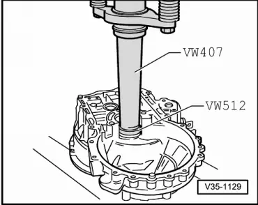
| t | Pressure pin -VW 407- |
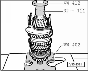
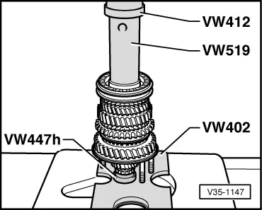
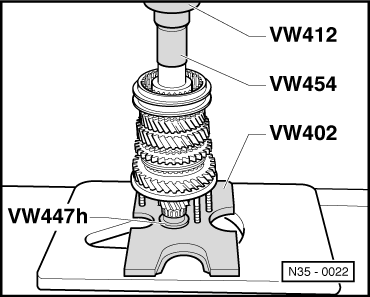
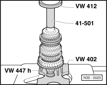
| t | Pressure disc -VW 412- |
| t | Pressure disc -VW 512- |
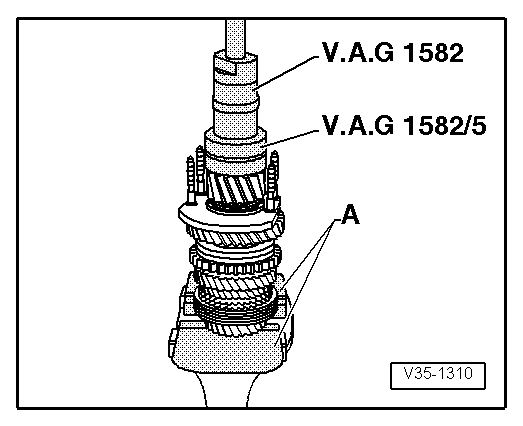
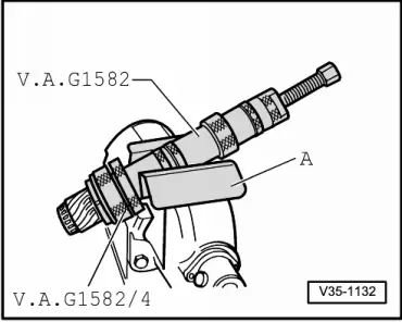
| t | Puller -VAG 1582- |
| t | Clamp -VAG 1582/4- |
| t | Clamp -VAG 1582/5- |

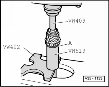
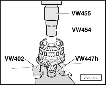
| t | Plate -VW 402- |
| t | Placer -32-111- |
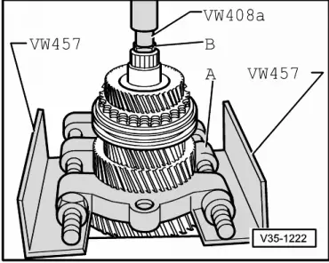
| t | Pressure pin -VW 408A- |
| t | Pressure pin -VW 409- |
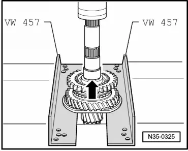
| t | Placer -VW 457- |
| t | Tube -VW 519- |

| t | Pressure ring -VW 429- |
| t | Tube -VW 415A- |
| t | Pressure disc -VW 447 H- |
| t | Pressure tube -VW 454- |
| t | Installation collar -VW 455- |
| t | Installation collar -41-501- |
 Note
Note
|
|

| 1 - | Hexagon nut, 25 Nm + 90° |
| q | 4 nuts for bearing support. |
| 2 - | Clutch housing |
| 3 - | Adjustment shim |
| q | For output shaft. |
| q | Adjustment overview → Chapter. |
| 4 - | Small taper roller bearing outer race |
| q | Remove → Fig. |
| q | Install → Fig. |
| 5 - | Small taper roller bearing inner race |
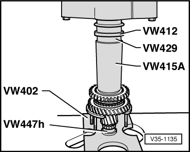
| q | Pull → Fig. |
| q | Install → Fig. |
| 6 - | Output shaft |
| q | Is paired with final drive gear, always renew together as a set. |
| q | Adjust → Chapter. |
| 7 - | Large taper roller bearing inner race |
| q | Remove → Fig. |
| q | Install → Fig. |
| 8 - | Thrust washer |
| q | Place sealing rings (Qty. 4) on the bearing support bolts. |
| 9 - | Bearing support |
| q | With large taper roller bearing outer race and bolts. |
| q | Only change outer race together with large taper roller bearing and bearing support. |
| 10 - | Thrust washer |
| q | Shoulder on thrust washer faces taper roller bearing. |
| 11 - | 1st gear wheel |
| 12 - | Needle roller bearing |
| q | For 1st gear. |
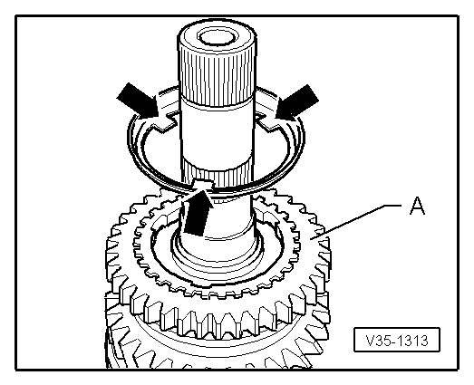
| 13 - | Synchro ring |
| q | (1st gear inner race) |
| q | Installation position → Fig. |
| q | Check wear → Fig. |
| q | Check lugs for wear marks. |
| 14 - | 1st gear outer race |
| q | Installation position → Fig. |
| q | Check wear → Fig. |
| q | Renew if scorched or worn. |
| 15 - | 1st gear synchro-ring |
| q | Installation position → Fig. |
| q | Check wear → Fig. |
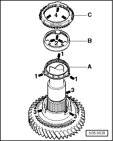
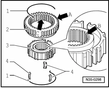
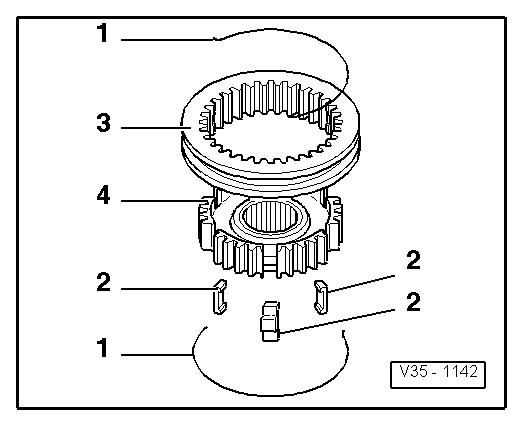
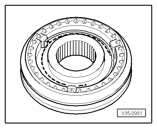
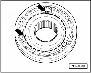
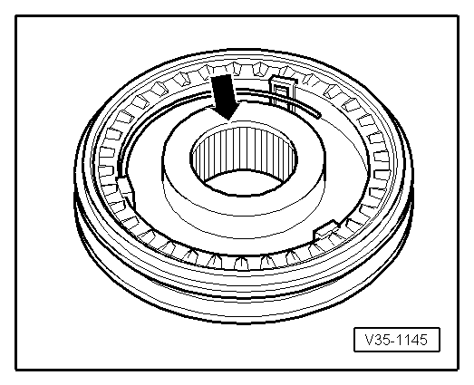
| 16 - | Locking collar of the 1st and 2nd gears with synchrohub |
| q | Pull off with bearing support after removing the circlip ( → Item) → Fig. |
| q | Disassemble → Fig. |
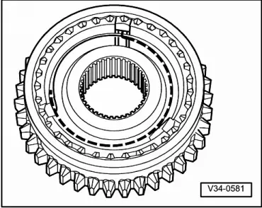
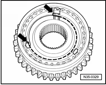
| q | Assemble locking collar/synchro hub → Fig., → Fig. and → Fig. |
| q | Installation position → Fig. |
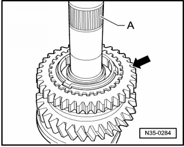
| q | Install → Fig. |
| 17 - | Circlip |
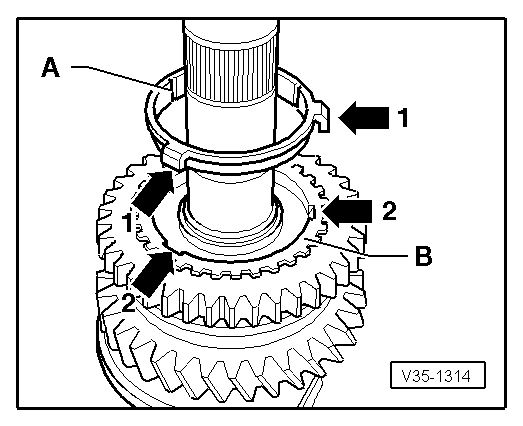
| 18 - | 2nd gear synchro-ring |
| q | Check wear → Fig. |
| q | Assemble so that the recesses locate in the locking collar locking pieces ( → Item). |
| 19 - | 2nd gear outer race |
| q | Install in synchro ring ( → Item), installation position → Fig. |
| q | Renew if scorched or worn. |
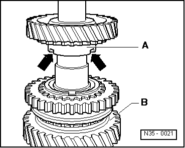
| 20 - | Synchro ring |
| q | (2nd gear inner ring) |
| q | Check wear → Fig. |
| q | Check lugs for wear marks. |
| q | Installation position → Fig. |
| 21 - | 2nd gear wheel |
| q | Installation position → Fig. |
| 22 - | Needle roller bearing |
| q | for 2nd gear. |
| 23 - | Thrust washer |
| 24 - | Sleeve for 3rd. gear needle roller bearing |
| q | Remove with 2nd gear wheel → Fig. |
| q | Install → Fig. |
| 25 - | Needle roller bearing |
| q | for 3nd gear |
| 26 - | 3rd gear wheel |
| 27 - | 3nd gear synchro-ring |
| q | Check wear → Fig. |
| 28 - | Locking collar of the 3rd and 4th gears with synchrohub |
| q | Remove with the gears for the 2nd gear ( → Item) and for the 3rd gear ( → Item) → Fig. |
| q | Disassemble → Fig. |
| q | Assemble locking collar/synchro hub → Fig. |
| q | Installation position locking collar/synchro hub → Fig. |
| q | Install → Fig. |
| 29 - | Bushing |
| q | For needle roller bearing. |
| q | Remove with the 3rd and 4th gear locking collar and synchro-hub ( → Item) → Fig. |
| q | Install → Fig. |
| 30 - | Needle roller bearing |
| q | For 4th gear. |
| 31 - | 4th gear synchro-ring |
| q | Check wear → Fig. |
| 32 - | 4th gear wheel |
| 33 - | Thrust washer |
| 34 - | Needle roller bearing |
| q | For output shaft. |
| q | Remove and install → Fig. |
| 35 - | Gearbox housing |
| 36 - | Bushing |
| q | For output shaft needle roller bearing. |
| q | Remove → Fig. |
| q | Install → Fig. |
| 37 - | 5th gear wheel |
| q | Remove and install → Chapter. |
| 38 - | Spring washer |
| q | Installation position . |
| 39 - | M10 Torx screw, 80 Nm |
| q | Fitted portion on bolt head holds saucer spring washer in position. |
|
|
|
|
|
|
|
|
|
|
|
|
|
|
Note
|
|
|
|
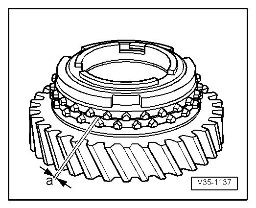
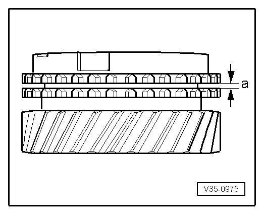
| Dimension “a” | New dimension | Wear limit |
| 1. and 2nd gear | 0,75 ... 1.25 mm | 0.3 mm |
|
|
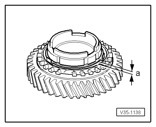
| Dimension “a” | New dimension | Wear limit |
| 1st and 2nd gears | 1,2 ... 1.8 mm | 0.5 mm |
Note
|
|
|
|
|
|
|
|
|
|
|
|
|
|
|
|
|
|
|
|
| Dimension “a” | New dimension | Wear limit |
| 1. gear 3. gear 4. gear | 1,0 ... 1,7 mm 1,0 ... 1,7 mm 1,0 ... 1,7 mm | 0,5 mm |
|
|
|
|
|
|
|
|
|
|
|
|
|
|