
Legend Coupe V6-3206cc 3.2L SOHC FI (1991)
Alternator FR Signal: Testing and Inspection
A/T Shift Position Signal
Before using this test procedure, verify the A/T shift position indicator illuminates in all gear positions. If the shift indicator does not function properly,
refer the chassis electrical diagrams for additional information.
1.
Turn ignition off.
2.
Install test harness between ECU and harness connector. If test harness is not available, carefully backprobe wires at ECU connector.
3.
Disconnect connector B from main harness only, leave connected to ECU.
4.
Turn ignition on.
A/T Shift Position Sensor Testing
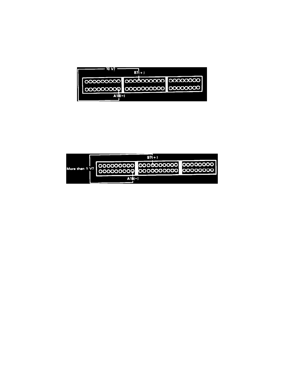
5.
Measure voltage between terminals B7 and A26.
Approx. 10 volts, proceed to next step.
Not approx. 10 volts, replace electronic control unit.
6.
Reconnect connector B to main harness.
A/T Shift Position Sensor Testing
7.
Measure voltage between terminals B7 and A26 with transmission in NEUTRAL.
More than 1 volt, proceed to next step.
Less that 1 volt, proceed to step 9.
8.
Repair open LT GRN wire between instrument cluster and ECU terminal B7.
9.
Measure voltage between terminals B7 and A26 with transmission in PARK.
More than 1 volt, proceed to next step.
Less that 1 volt, proceed to step 11.
10.
Replace shift position switch. End of test.
11.
Measure voltage between terminals B7 and A26 with transmission in DRIVE.
Approx. 10 volts, proceed to step 13.
Not approx. 10 volts, proceed to next step.
12.
Repair shorted LT GRN wire between instrument cluster and ECU terminal B7. End of test.
13.
A/T shift position signal normal.