
Legend Coupe V6-3206cc 3.2L SOHC FI (1991)
Alternator FR Signal: Testing and Inspection
Alternator "FR" Signal
1.
Install test harness between ECU and connector. If test harness is not available, carefully backprobe wires at ECU connector.
2.
Disconnect ECU connector D from main harness only.
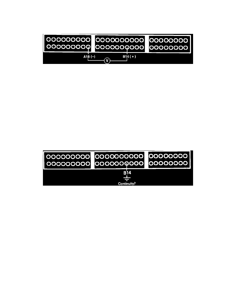
Alternator FR Signal Testing
3.
With ignition on, measure voltage between ECU terminals A26 and D9.
5 volts, proceed to step 5.
Not 5 volts, proceed to next step.
4.
Replace electronic control unit. End of test.
5.
Turn ignition off and reconnect ECU connector D to harness.
6.
Start engine and run until cooling fan comes on.
7.
With voltmeter still connected between ECU terminals A26 and D9, turn on headlamps and rear defogger.
Voltage decreased, proceed to next step.
No voltage decrease, proceed to step 9.
8.
Alternator FR signal if normal, no further testing required.
9.
Stop engine and disconnect ECU connector D from ECU only.
10.
Disconnect negative battery cable.
Alternator FR Signal Testing
11.
Check for continuity to ground on harness terminal D9.
Continuity, proceed to next step.
No continuity, proceed to step 15.