
TL V6-3.5L (2007)
Data Link Connector: Testing and Inspection
Part 2
DLC Circuit Troubleshooting (Part 2)
1. Inspect the No. 8 FI ECU (ECM/PCM) (15 A) fuse in the under-hood fuse/relay box.
Is the fuse OK?
YES -
-
J32A3 engine: Go to step 8.
-
J35A8 engine: Go to step 21.
NO - Go to step 2.
2. Remove the blown No. 8 FI ECU (ECM/PCM) (15 A) fuse from the under-hood fuse/relay box.
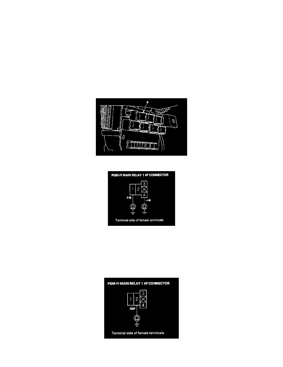
3. Remove the left kick panel, then remove PGM-FI main relay 1 (B) from the under-dash fuse/relay box.
4. Check for continuity between body ground and PGM-FI main relay 1 4P connector terminals No. 1 and No. 4 individually.
Is there continuity?
YES - Repair short in the wire between the No. 8 FI ECU (ECM/PCM) (15 A) and PGM-FI main relay 1. Also replace the No. 8 FI ECU
(ECM/PCM) (15 A) fuse.
NO - Go to step 5.
5. Disconnect each of the components or connectors below, one at a time, and check for continuity between PGM-FI main relay 1 4P connector
terminal No. 2 and body ground.