
Functional description
- Make
- Alfa Romeo
- Model
- 145/146 Electrical System Diagnosis Manual, Volume 3
- Year
- 1994–2001
- Section
- Anti Theft Device › Functional description
FUNCTIONAL DESCRIPTION
The anti-theft system is controlled by electronic control unit N45 integrated with the siren and the emergency key.
The control unit is supplied directly by the battery at pin A3; the key-operated supply reaches pin B12. Through fuse F1 of fusebox G1 pin B7 is supplied (blinker supply).
Pin A9 is earthed (G53b).
The system activation signal is sent from the receiver N67 to pin A2 of the control unit; the same serial connection line is used to control the volumetric sensors, inserted with the receiver inside the ceiling light.
Through the receiver N67 door opening/closing is controlled, by means of the door lock control unit N11 of fusebox G1 (for further details see "Door locking System").
The control unit controls the closing of doors and bonnets via switches P11 and P10 of the doors (which are the same for the door locking device) which send an earth respectively to pins B8 and B9. The bonnet is controlled by switch H44, which is connected at pin B18, and the luggage compartment by switch H24 (the same that turns on the luggage compartment light) which is connected at pin B17.
In addition to the closing of the doors, carried out directly by the receiver N67, the control unit activates the blinkers (hazard warning lights flashing) sending an intermittent signal: from pin B1 for the right-hand lights and from pin B2 for the left-hand lights.
Pin A1 of the control unit sends a duty-cycle signal to led D31 when conditions so require.
ONLY FOR VERSIONS WITHOUT ALFA ROMEO CODE : the anti-theft system "intercepts" the key in the STARTING position signal (pin B6) which is "referred" to the starter motor A11 (from pin B5) only if the system is not in an alarm condition.
In addition, in the case of alarm, the injection control unit supply is inhibited; this supply (12 V) reaches pin B4 and it is "returned" by pin B3 (Boxer 1.3 and 1.6 versions).
Pin A10 sends a specific block signal to the control unit (only Boxer 1.7 16V version).
For further details see the sections concerning engine ignition/injection.
For the TD version, the key-operated supply for the engine stop solenoid valve and glow plugs reaches pin B4, and it is "returned" by pin B3. For further details see "TD engine control devices".
Lastly the system can be connected with the Alfa Romeo Tester through connector T7; the diagnosis signal - line K - leaves from pin A6 of the control unit.
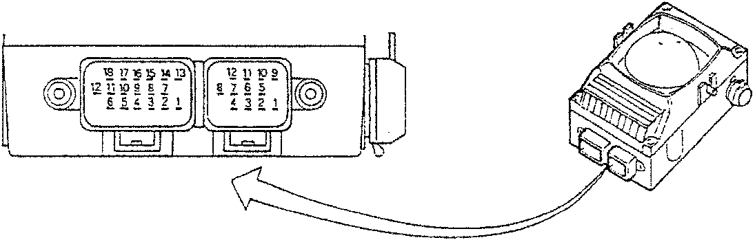
ANTI-THEFT CONTROL UNIT PIN-OUTS
A1 Signalling led control
A2 Serial connection line with receiver (ceiling light)
A3 Direct supply
A4 N.C.
A5 N.C.
A6 Diagnosis line K
A7 N.C.
A8 N.C.
A9 Control unit earth
(*) A10 Engine control inhibition (only for Boxer 1.7 16v)
A11 N.C.
A12 N.C.
B1 RH direction indicators control
B2 LH direction indicators control
(*) B3 Fuel pump/injection supply consensus (Boxer 1.3 and 1.6) - "key-operated" supply for engine electric stop and glow plug warming (TD)
(*) B4 Fuel pump/injection supply consensus (Boxer 1.3 and 1.6) - "key-operated" supply for engine electric stop and glow plug warming (TD)
(*) B5 Starter motor supply
(*) B6 STARTING signal from ignition switch
B7 Blinker supply
B8 LH door open signal
B9 RH door open signal
B10 N.C.
B11 N.C.
B12 "Key-operated" supply
B13 N.C.
B14 N.C.
B15 N.C.
B16 N.C.
B17 Tailgate open signal
B18 Tailgate closed signal
(*) Connected only for versions without ALFA ROMEO CODE
Parts & tools for this job For 1994 Alfa Romeo 145/146
- TOOLDigital multimeterSearch: automotive digital multimeter
- PARTAssorted fuse kitSearch: car fuse assortment kit
- TOOLWire crimper and connector kitSearch: wire crimper connector kit
Links open Amazon search results in a new tab. As an Amazon Associate I earn from qualifying purchases.