
General description
- Make
- Alfa Romeo
- Model
- 145/146 Electrical System Diagnosis Manual, Volume 3
- Year
- 1994–2001
- Section
- Anti Theft Device › General description
GENERAL DESCRIPTION
Upon request the car is pre-wired for the installation of an alarm system, combined with the door locking system with remote control.
The V.A.S.( Vehicle Alarm System) is a system which offers both both perimeter and interior protection: it is able to survey the state of the doors and note the presence of foreign bodies inside the passenger compartment; the system is controlled by a single compact unit which comprises the electronic control unit and siren.
The system is "universal" as it offers the possibility to configure the control unit according to the requirements of the different countries (alarm sound level and types of light flashing for activation/deactivation).
In addition, a sophisticated self-diagnosis system controls:
- intermittent and permanent errors or faults;
- number of activations of the anti-theft device and the number of alarms sounded;
- specific faults of the control unit;
WARNING: For the 145 the alarm system is supplied in two different versions:
- cars without ALFA ROMEO CODE: V.A.S. ALARM system_with volumetric. perimetal protection and internal counter measures in the event of alarm (engine and starter motor lock);
- cars with ALFA ROMEO CODE: V.A.S. ALARM system_with volumetricand perimetal protection: without engine control carried out by the above-mentioned system (see the corresponding section "ALFA ROMEO CODE").
COMPONENTS
The transmitter, protected by a shockproof rubber cover, comprises a printed circuit and an infrared ray sender; it is battery-powered (2 3V lithium batteries) and, each time the control button is pressed, it sends a beam of rays in the direction in which it is pointed. This infrared ray device continuously transmits the code for the whole time in which the button is pressed. An indicator (led) turns on each time a signal is emitted.
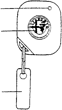
Transmitter
- Luminous led
- Control button
- Transmitter code label
The receiver, incorporated in the front ceiling lamp, is an electronic device that picks up the infrared ray signal through a half-ball protruding from the receiver. There is also a led on the receiver which lights up when the signal is received, while a special button makes it possible to memorise the secret control code. The special half round shape makes it possible to capture the signal through 360 degrees, provided that the transmitter is no more than 5 metres away
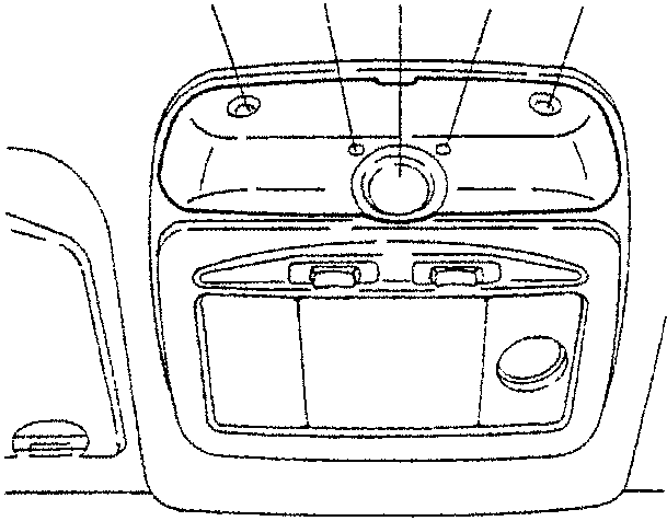
Receiver and volumetric sensors
- Half-ball receiver
- Luminous led
- Memorising button
- Volumetric sensors
Parts & tools for this job For 1994 Alfa Romeo 145/146
- TOOLDigital multimeterSearch: automotive digital multimeter
- PARTAssorted fuse kitSearch: car fuse assortment kit
- TOOLWire crimper and connector kitSearch: wire crimper connector kit
Links open Amazon search results in a new tab. As an Amazon Associate I earn from qualifying purchases.