
General description
- Make
- Alfa Romeo
- Model
- 145/146 Electrical System Diagnosis Manual, Volume 3
- Year
- 1994–2001
- Section
- Wing Mirror Adjustment › General description
GENERAL DESCRIPTION
The two wing mirrors are adjusted through the special switch which controls the two electric motors located inside each mirror (one motor turns the mirror on horizontally, the other vertically).
A single switch operates both the left and right mirrors, as a selector makes it possible to switch from one to the other.
FUNCTIONAL DESCRIPTION
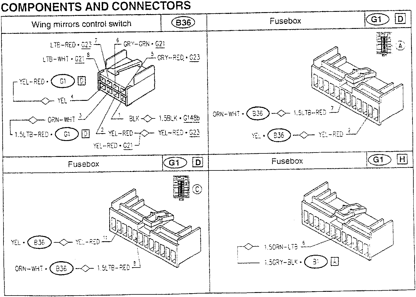
The double switch B36 controls the two electric motors located in the mirrors P8 (left) and P9 (right).
The switch is "turn-key" supplied - pin 3 - through fuse F15 of fusebox G1; pin 1 is earthed.
By actuating the switch B36 in one of the possible directions, positive and earth signals are sent to one of the two motors, in addition to the shared signal - pin 2 -, thereby determining the direction of rotation. Depending on the position of the selector, the right motors P9 (signals leaving pins 6 and 8 of B36) or the left ones P8 (signals from pins 5 and 7 of B36) are connected; the switch is illuminated by a led, which is turned on when the side lights are on - pin 4 - (also see "Lighting and indicators").
COMPONENTS AND CONNECTORS
| Wing mirrors control switch | B36 | Fusebox | G1 D |
|---|---|---|---|
Parts & tools for this job For 1994 Alfa Romeo 145/146
- TOOLTrim removal tool kitSearch: trim removal tool kit
- PARTTouch-up paintSearch: Alfa Romeo touch up paint
- PARTPanel clip assortmentSearch: Alfa Romeo panel clips assortment
Links open Amazon search results in a new tab. As an Amazon Associate I earn from qualifying purchases.