
System
- Make
- Alfa Romeo
- Model
- 145/146 Factory Service Manual
- Year
- 1994–1999
- Section
- Heating and ventilation - Boxer engines › System
SYSTEM
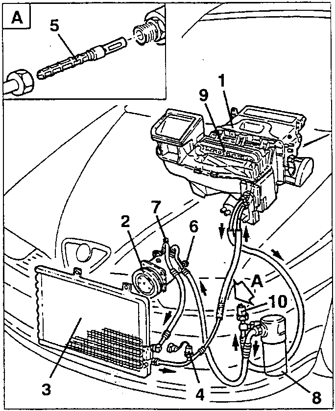
- Heating and ventilation Unit
- Compressor
- Condenser
- Three-level pressure switch (trinary)
- Expansion valve
- Needle valve for draining/recharging R134a on the low pressure pipe
- Needle valve for draining/recharging R134a on the high pressure pipe
- Drier filter
- Evaporator
- Minimum pressure switch
DESCRIPTION
The heating and ventilation system for the models with boxer engines is substantially the same as the one fitted on the model with turbodiesel engine.
The main differences from this system are the following:
- the adoption of a compressor with fixed rather than variable displacement;
- the adoption of a minimum pressure switch;
- different positioning of the system components in the engine compartment.
BELOW ARE GIVEN THE VARIANTS (FOR EXAMPLE THE MONOGRAPHIC PARTS AND PROCEDURES) TO THIS SYSTEM IN RELATION TO THE TURBODIESEL VERSION
STRATEGY FOR CONNECTING AND DISCONNECTING THE COMPRESSOR
The compressor is controlled by the engine electronic injection management system which adapts the idle speed when the compressor is connected, or it cuts off the connection.
IAW injection system management
In addition to adapting the idle speed each time the compressor is connected, this injection system temporaneously disables (appr. 10 sec) the compressor connection if high engine power is required.
MP3.1 injection system management
This injection system only adapts the engine idle speed each time the compressor is connected.
M2.10.3 injection system management
The injection system control unit carries out the following strategies:
- it adapts the engine idle speed each time the compressor is connected; if the engine speed falls below 700 rpm, the compressor is disconnected;
- in the need for high power (high speed - above 6000 rpm engine at full load - max throttle opening) it momentaneously cuts off the supply to the compressor;
- it does not allow the compressor to be connected when starting the engine until normal operating conditions have been reached.
DESCRIPTION OF THE MAIN COMPONENTS OF THE AIR CONDITIONING SYSTEM
MINIMUM PRESSURE SWITCH
The purpose of the minimum pressure switch is to de-energize the electromegnetic joint of the compressor pulley when the pressure (in the accumulator) reaches a mean rating of 1.72 bar re-energizing it again when the pressure reaches the mean rating of 3.17 bar, in order to maintain the cold required and to prevent the evaporator from freezing.
It also protects the compressor disconnecting the electromagnetic joint from its pulley when the pressure of the refrigerant falls below 1.58 bar due to a leak or when the environment temperature falls below 2.7°C.
Parts & tools for this job For 1994 Alfa Romeo 145/146
- PARTEngine gasket setSearch: Alfa Romeo 145/146 1994 engine gasket set
- TOOLTorque wrenchSearch: 3/8 inch torque wrench
- TOOLFeeler gauge setSearch: feeler gauge set
Links open Amazon search results in a new tab. As an Amazon Associate I earn from qualifying purchases.