
FUNCTIOnAL DESCRIPTION
- Make
- Alfa Romeo
- Model
- 155 Factory Service Manual
- Year
- 1992–1998
- Section
- FUNCTIOnAL DESCRIPTION › FUNCTIOnAL DESCRIPTION
FUNCTIOnAL DESCRIPTION
ELECTRIC FAN
The heating and ventilation electric fan Q1 is supplied by "key-activated" power through relay Q15; this receives supply directly from the battery through the general fuse of the air conditioning system Q43 (50A) and relay I35 and fuse F13 (20 A) are activated by a key activated voltage originating from the fusebox G1.
The motor of the electric fan Q1 is operated with an earth signal originating from the control knob Q4. This signal crosses the speed regulator Q5 composed of three resistances which determine the four different speeds depending on the signal coming from the knob: from pin 2 of connector B (1st speed), from pin 1 of connector B (2nd speed), from pin C of connector A (3rd speed), or from pin B of connector A (4th speed), this is a direct signal which does not pass Q5.
When the control knob Q4 is in the "0" position the electric fan is off but is operated at the first speed if the compressor is engaged. In this case relay Q69 controls the supply to the electric fan at the first speed. This relay, with a key-activated power supply, is activated by the same earth signal which controls the engagement of the compressor (from switch Q68 across pins 7 and 8 of connector B to knob Q4) and sends a signal to regulator Q5 corresponding to the 1st speed.
NOTE: The regulator Q5 has a built-in tensiometric safety switch which deactivates the circuit if the temperature exceeds 90±5°C due to power overloading.
RECIRCULATION FUNCTION
The recirculation function is obtained by operation of the button Q68 which commands the motor Q27 according to the following power supply logic (pin 2 of Q27 is earthed):
- with switch Q4 in the OFF position, 12 V to pin 3 of Q27: Recirculation engaged;
- with switch Q4 to "0", "1", etc... and switch Q68 not pressed, 12 V to pin 1 of Q27: Recirculation not engaged;
- with switch Q4 to "0", "1", etc... and switch Q68 pressed, 12 V to pin 3 of Q27: Recirculation engaged.
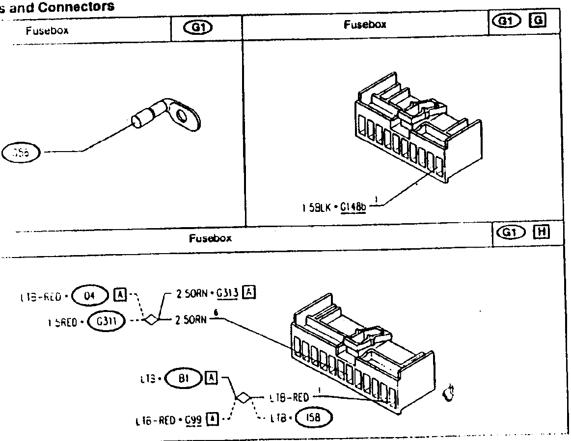
Component and Connectors
| Fusebox | G1 | Fusebox | G1 G |
|---|---|---|---|
| 10 Ω·G5a | 1 5BLK · G14Bb | G1 H | |
| L T6-RED · Q4 A | 2 5ORN · G313 A | 1 5RED · G311 | 2 5ORN |
| L T3 · B1 A | L T6-RED · G99 1 | L T6-RED | 158 |
Parts & tools for this job For 1992 Alfa Romeo 155
- TOOLA/C manifold gauge setSearch: AC manifold gauge set
- TOOLUV leak detection kitSearch: AC UV leak detection kit
- PARTCabin filterSearch: Alfa Romeo 155 1992 cabin filter
Links open Amazon search results in a new tab. As an Amazon Associate I earn from qualifying purchases.