Workshop Manuals Factory service & repair Alfa Romeo
01 Introduction and contents02 Vehicle characteristics and maintenance03 Engine – mechanical (Twin Spark)04 Fuel system (Twin Spark)05 Ignition, starting and charging (Twin Spark)06 Engine cooling (Twin Spark)07 Engine – mechanical (V6)08 Fuel system (V6)09 Ignition, starting and charging (V6)10 Engine cooling (V6)11 Electrical diagnosis – introduction and wiring diagram guide12 Electrical 01 – Power supply13 Electrical 02 – Fusebox14 Electrical 03 – Location of grounds15 Electrical 04 – Sidelights16 Electrical 05 – Main and dipped beam headlights17 Electrical 06 – Headlight alignment adjustment18 Electrical 07 – Rear and front fog lamps19 Electrical 08 – Direction indicators and hazard warning lights20 Electrical 09 – Stop lights21 Electrical 10 – Reversing lights22 Electrical 11 – Day lights23 Electrical 11A – Dim-dip device24 Electrical 12 – Interior lighting25 Electrical 13 – Instrument panel26 Electrical 14 – Check panel27 Electrical 15 – Provision for radio28 Electrical 15A – Radio system29 Electrical 16 – Cigar lighter30 Electrical 17 – Horns31 Electrical 18 – Windscreen wipers and washers, headlight washers32 Electrical 19 – Heated rear window and heated door mirrors33 Electrical 20 – Boot release control34 Electrical 21 – Door locking system35 Electrical 21A – Remote control door locking36 Electrical 21B – Anti-theft device37 Electrical 22 – Front power windows38 Electrical 22A – Front power windows (one-touch version)39 Electrical 23 – Rear power windows40 Electrical 24 – Adjustable heated seats41 Electrical 25 – Sunroof42 Electrical 26 – Heating, ventilation and air conditioning43 Electrical 27 – Starting and charging44 Electrical 28 – Engine cooling fan45 Electrical 29 – Motronic ignition and injection46 Electrical 29A – Alfa Romeo CODE immobiliser47 Electrical 30 – ABS48 Electrical 31 – Controlled damping suspension49 Electrical diagnosis – components key50 Clutch51 Gearbox and differential52 Axle shafts53 Front suspension54 Brakes55 Steering56 Rear suspension57 Wheels and tyres58 Electrical system59 Instrument panel and electronic instruments60 Bodywork61 Doors62 Boot and bonnet63 Interior trim64 External trim65 Heating and ventilation
Alfa Romeo 155 Factory Service Manual (1992-1998)03 · Engine – mechanical (Twin Spark)
03 · Engine

Crankshaft: (page 2 of 2)

Make
Alfa Romeo
Model
155 Factory Service Manual
Year
1992–1998
Section
Moving parts & auxiliary organs
Engine – mechanical (Twin Spark)Crankshaft: · page 2 of 2

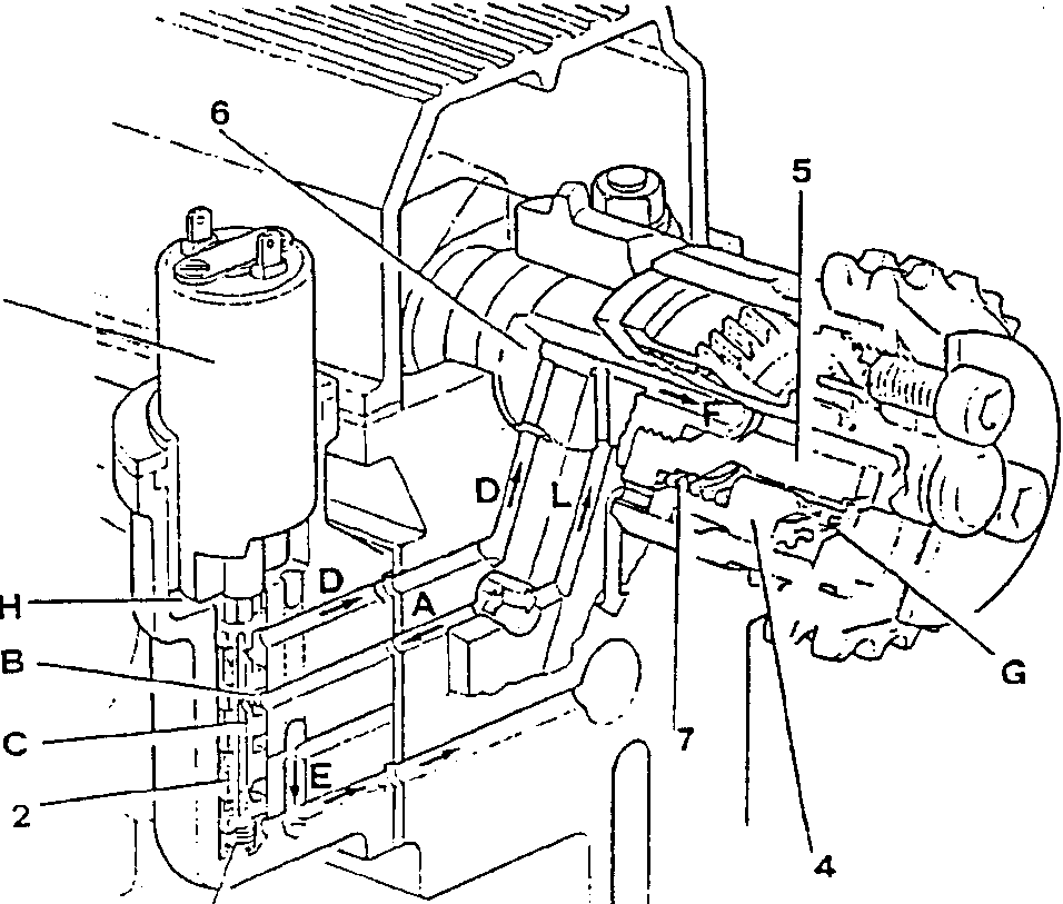
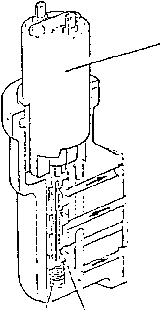
When the quantity of air taken in by the engine is lower than a pre-set value, the solenoid (1) is deactivated and the valve box (2) pushed by the counter-spring (3) is lifted up allowing the passage of oil from the channeling (A) to reach the variator. In this case the timing of the intake valves is not changed.

If the quantity of intake air exceeds the pre-set value, the solenoid (1) is activated and pushes the valve box (2) downwards. In this position the oil arriving from the channeling (A) enters the piston chamber (B) and passes through a hole into the internal channel (C) in the piston. The oil can only exit this channel through the upper hole (leading to the oil-to-variator delivery duct (D)) as the lower hole no longer opens onto the exhaust duct (E) as the valve box (2) is lowered. The oil passes through the channeling (D) and (F) and reaches the chamber (G) moving the piston (4) axially towards the engine.

The piston is externally equipped with helical teeth and as a result of the axial movement is forced to rotate clockwise (as seen from the timing side). This rotation is transmitted to the pinion through a straight toothed grooved profile. The pinion (5) which is rotated by the threaded tug of the camshaft (6) transmits the rotation to the shaft, and in this way the timing of the intake valves is varied by 30°.

When the solenoid is deactivated, the valve box (2) returns to the initial position, interrupting the flow of pressurized oil to the piston (4) but permitting the return of the oil to the outlet due to the thrust from the counter spring (7).

The channeling (L) enables the camshaft journal to be lubricated under the various operating conditions.

The oil which leaks into the solenoid chamber (H) is discharged through the drainage hole (E).
Cylinder head valve train assembly diagram
Engine main mechanical unit diagram showing components 1-7, A-G, and H-E with channeling L.
  1. solenoid
  2. valve box
  3. counter-spring
  4. piston
  5. pinion
  6. camshaft
  7. counter spring

Parts & tools for this job For 1992 Alfa Romeo 155

Links open Amazon search results in a new tab. As an Amazon Associate I earn from qualifying purchases.