
Checks and inspections
- Make
- Alfa Romeo
- Model
- 155 Factory Service Manual
- Year
- 1992–1998
- Section
- Throttle body - throttle potentiometer › Checks and inspections
- Unscrew the retaining screws and separate the air cleaner cover from the air flow meter.
- Remove the gasket.
- Remove the relative support bracket from the air flow meter.
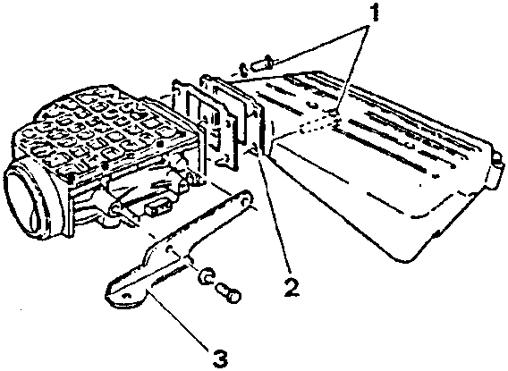
CHECKS AND INSPECTIONS
- Press on the shutter of the air flow meter and check that it rotates easily, that there are no friction points up to the stop limit and that it is not scored or or dirty.
- If necessary clean the internal surfaces of the air flow meter with a clean, fibreless cloth.
- For a functional check of the electrical components (potentiometer, sensors etc.) refer to the ELECTRICAL - ELECTRONIC DIAGNOSIS manual.
NOTE: Never operate the air flow meter unless it is connected to the control unit.
THROTTLE BODY - THROTTLE POTENTIOMETER
The throttle body regulates the quantity of air sent to the air intake box in relation to the position of the accelerator pedal. The accelerator cable acts on a pulley sector locked onto the rotation pin of the throttle valve.
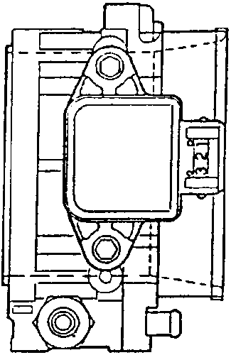
A spiral spring permits the return of the throttle valve to the closed position.
The throttle potentiometer is located to one side and is fixed to the rotation pin of the throttle. It is composed of a potentiometer of which the mobile part is controlled directly by the shaft of the throttle valve. During operation, the control unit supplies the potentiometer with 5 volts applied to pins (1) and (2).
A voltage collects on pin (3) which is inversely proportional to the position of the throttle valve. On the basis of the voltage sent by pin (3), the control unit recognizes the degree to which the valve has opened and corrects the mixture accordingly.
When the throttle valve is closed, an electric signal of ~ 0.5 Volts reaches the control unit which recognizes the idle and cut-off states (distinguished on the basis of engine r.p.m.).
The potentiometer automatically recognizes the stop limit of the throttle when it is at idle speed by way of a "self-adaptation" function. This eliminates the operations of regulation carried out on the potentiometer and over a period of time makes it possible to detect any wear affecting the closed position of the throttle valve.
Parts & tools for this job For 1992 Alfa Romeo 155
- TOOLTrim removal tool kitSearch: trim removal tool kit
- PARTTouch-up paintSearch: Alfa Romeo touch up paint
- PARTPanel clip assortmentSearch: Alfa Romeo panel clips assortment
Links open Amazon search results in a new tab. As an Amazon Associate I earn from qualifying purchases.