
Description
- Make
- Alfa Romeo
- Model
- GTV / Spider GTV and Spider (916) Factory Service Manual
- Year
- 1995–2000
- Section
- Engine cooling system › Description
DESCRIPTION
The cooling system is of the sealed type with forced circulation by a centrifugal pump (1) located on the cylinder head and operated by the timing gear belt. A thermostatic valve (2), fitted on the rear of the engine keeps the engine temperature at an optimum level; it opens when the coolant reaches a temperature of 83 °C.
The radiator (4) cools the engine fluid by the dynamic air and also by a fan (3) which is turned on:
- for versions with M2.10.3 injection-ignition system, by a thermal contact (5) on the radiator;
- for versions with M2.10.4 injection-ignition system, directly by the MOTRONIC control unit, depending on the signal received from the engine coolant temperature sensor (NTC).
(For further details about how the fan works, see ELECTRIC-ELECTRONIC DIAGNOSIS - Sect. 26 for versions with air conditioner and Sect. 27 for versions without air conditioner).
The expansion tank (7) tops up the circuit if the level falls and absorbs the changes in the volume of the coolant due to changes in temperature: it also vents air from the circuit.
The circuit is fitted with a coolant fluid temperature sender for the max. temperature gauge and thermal contact (9) for the warning light.
WATER PUMP
The water pump is of the centrifugal type with blades. It is fastened to the cylinder head and operated by the crankshaft via the timing gear belt. An O-Ring ensures tightness between the cylinder head and the pump. The water pump is kept running constantly to ensure that the coolant fluid circulates continuously.
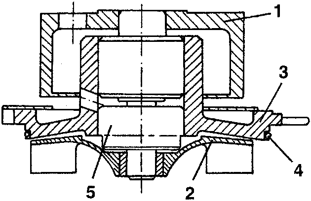
- Pulley
- Impeller
- Pump casing
- O-Ring
- Bearing
OPERATION OF THE CIRCUIT
After the fluid has cooled the engine, it leaves the cylinder head and reaches the thermostatic unit (92). From here, if the temperature is below 83 °C, it is drawn into the pump (1) through a longitudinal coolant return manifold located on the left-hand side of the cylinder head.
Conversely, if the temperature exceeds this value, the fluid is directed to the radiator (4) through the opening of the thermostat.
After being cooled in the radiator, the fluid returns, still through the longitudinal manifold, to the pump which directs it to the engine.
From the thermostatic cup the fluid is also sent to:
- - heat the throttle body (8) from which it flows to the expansion tank (7) also venting air from the system;
- - the climate control system heater (6) from which it returns to the longitudinal manifold;
- - the heat exchanger (12) for cooling the engine oil before being ducted directly into the longitudinal manifold through which it returns to the pump.
The expansion tank supplies the engine cooling system via a special pipe connected with the longitudinal manifold.
REMOVAL/REFITTING
- Set the car on a lift.
- Disconnect the battery (-) terminal.
- Remove the right front wheel and mud flap.
- Raise the car and working as illustrated on the belt tensioner loosen the tension of the auxiliary components drive belt and remove it.
- Slacken the four fastening screws and remove the auxiliary components drive pulley.
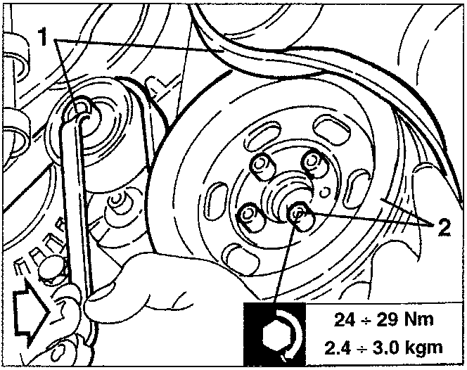
24 ÷ 29 Nm
2.4 ÷ 3.0 kgm
Parts & tools for this job For 1995 Alfa Romeo GTV / Spider
- PARTEngine gasket setSearch: Alfa Romeo GTV / Spider 1995 engine gasket set
- TOOLTorque wrenchSearch: 3/8 inch torque wrench
- TOOLFeeler gauge setSearch: feeler gauge set
Links open Amazon search results in a new tab. As an Amazon Associate I earn from qualifying purchases.