
Control unit-siren
- Make
- Alfa Romeo
- Model
- GTV / Spider GTV and Spider (916) Factory Service Manual
- Year
- 1995–2000
- Section
- Alarm system › Control unit-siren
55 Electric systemControl unit-siren
For the description and diagnosis of this system refer to "Group 55 - ELECTRIC SYSTEM DIAGNOSIS - Section "Alarm System".
CONTROL UNIT-SIREN
REMOVAL/REFITTING
- With the alarm deactivated, disconnect the battery.
- Open the bonnet and remove the engine compartment right-hand cover (see Group 70).
- Slacken the screw fastening the bracket supporting the climate control unit and the alarm system control unit-siren.
- Slacken the bolt.
- Remove the bracket complete.
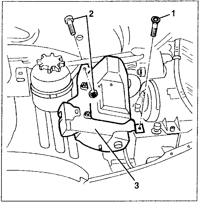
- Overturn the bracket.
- Slacken the nuts.
- Open the support tabs and remove the control unit-siren group.
- Disconnect the connections and retrieve the group.
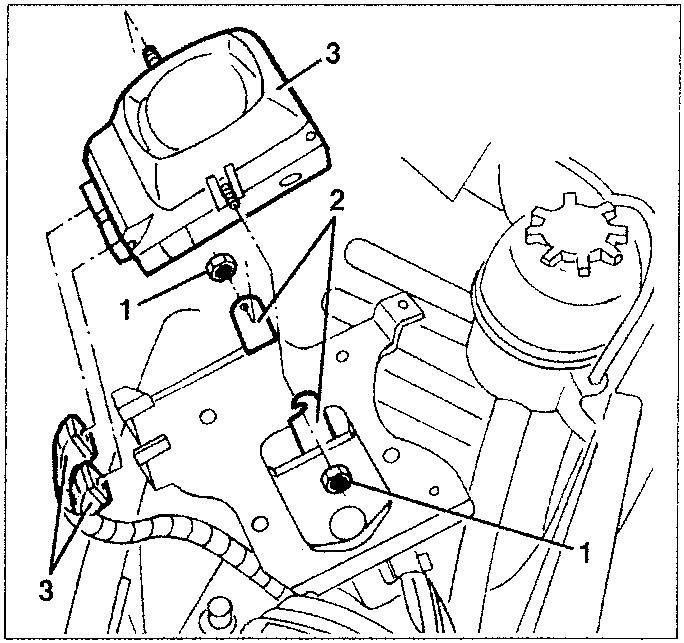
Refit the control unit-siren group reversing the sequence followed for removal.
REMOTE CONTROL RECEIVER UNIT
- Disconnect the battery.
- Remove the passenger compartment roof lamp (see specific paragraph).
- Slacken the two screws fastening the frame.
- Remove the frame.
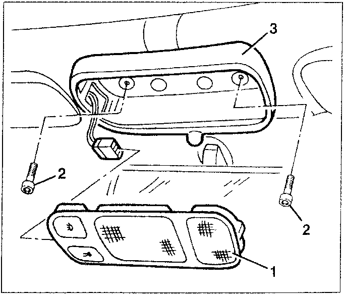
Parts & tools for this job For 1995 Alfa Romeo GTV / Spider
- TOOLTorque wrenchSearch: 3/8 inch torque wrench
- TOOLSocket setSearch: socket set metric
- BOOKHaynes manualSearch: Haynes manual Alfa Romeo GTV / Spider
Links open Amazon search results in a new tab. As an Amazon Associate I earn from qualifying purchases.