
Injection-ignition control unit
- Make
- Alfa Romeo
- Model
- GTV / Spider GTV and Spider (916) Factory Service Manual
- Year
- 1995–2000
- Section
- Electronic control units › Injection-ignition control unit
WARNING: The following pages describe the procedures necessary for removing and refitting the electronic control units fitted on the vehicle with the exception of some devices inserted directly in the fusebox. For the location of the various devices (control units, relays, etc.) and for any other functional information see "Group 55 - ELECTRIC SYSTEM DIAGNOSIS".
INJECTION-IGNITION CONTROL UNIT
REMOVAL/REFITTING
- Disconnect the battery
- Remove the glove box (see specific paragraph).
- Working under the dashboard on the right-hand side panel of the passenger compartment, move the trim aside.
- Slacken the two nuts
- Detach the control unit from the side panel
- Disconnect the combs and retrieve the control unit.
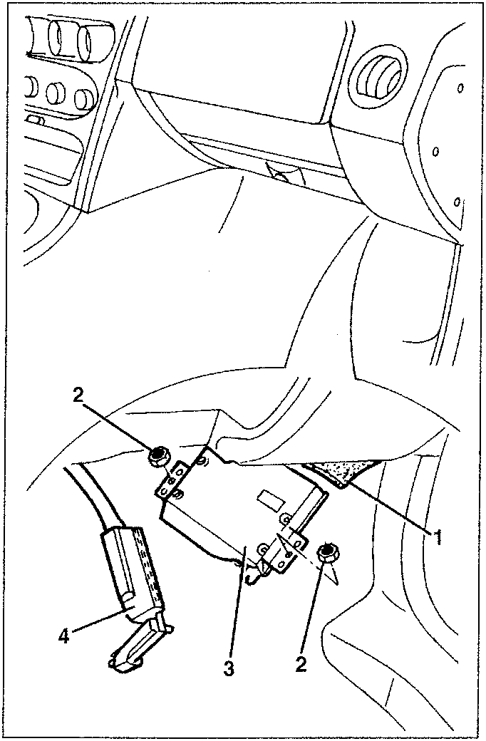
- Component 1
- Component 2
- Component 3
- Component 4
ABS CONTROL UNIT
The ABS control unit is integrated in the hydraulic unit of the ABS system. For removal and refitting procedures see Group 33 - Brakes.
ALARM SYSTEM CONTROL UNIT
The alarm system control unit is integrated with the siren and cannot be removed separately. For removal and refitting procedures see specific paragraph "Alarm System".
AIR BAG AND PRE-TENSIONER CONTROL UNIT
For removal and refitting procedures see specific paragraph "Air Bag and pre-tensioners".
POWER WINDOW CONTROL UNIT (*)
REMOVAL/REFITTING
- Disconnect the battery.
- Using tool 1.823.025.000 rotate the three bayonet pins fastening the fusebox cover.
- Remove the fusebox cover.
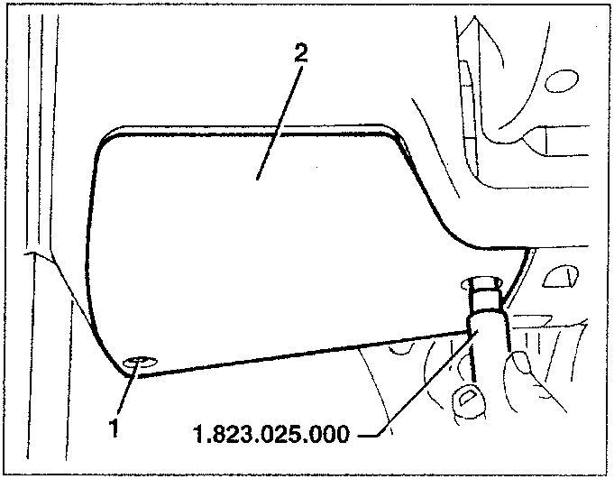
(*) From the '97 version the "integrated services" control unit has been replaced. The REMOVING/REFITTING procedure remains unchanged.
Parts & tools for this job For 1995 Alfa Romeo GTV / Spider
- TOOLTorque wrenchSearch: 3/8 inch torque wrench
- TOOLSocket setSearch: socket set metric
- BOOKHaynes manualSearch: Haynes manual Alfa Romeo GTV / Spider
Links open Amazon search results in a new tab. As an Amazon Associate I earn from qualifying purchases.