
Turbocharger
- Make
- Alfa Romeo
- Model
- GTV / Spider GTV and Spider (916) Factory Service Manual
- Year
- 1995–2000
- Section
- Air supply system › Turbocharger
TURBOCHARGER
This substantially comprises two impellers splined onto the same shaft, which turns on two special lubricated supports through two branches (input and output) of the lubrication circuit of the engine.
Two special pipes (6 - 7) branched from the engine cooling circuit are connected to the turbocharger and their purpose is to disperse most of the heat released by the turbine exhaust gas.
An impeller (3) "turbine", connected to the exhaust manifolds (9), is turned by the energy still possessed by the exhaust gas ducted to it. The turbine sets into motion, at the same speed, the other impeller (4) "compressor" which is connected to the intake manifold.
Due to its speed of rotation and the particular shape of the blades, the charger withdraws outside air and compresses it in the intake manifold, consequently in the cylinders of the engine.
If the engine increases the number of revolutions, also the turbine and the charger increase their speed of rotation thereby increasing the quantity of air delivered to the engine.
On the turbocharger there is a Waste-Gate valve (2) which, through a command from the Pierburg solenoid valve, allows part of the exhaust gas to by-pass (or not to by-pass) the turbine depending on the engine's need for power/torque.
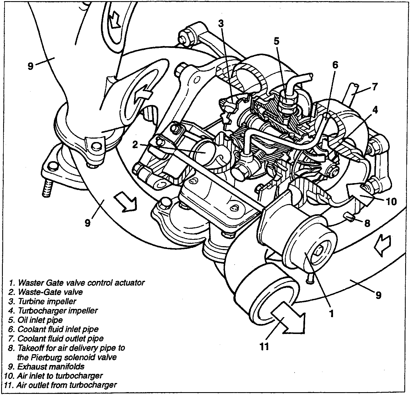
- Waster Gate valve control actuator
- Waste-Gate valve
- Turbine impeller
- Turbocharger impeller
- Oil inlet pipe
- Coolant fluid inlet pipe
- Coolant fluid outlet pipe
- Takeoff for air delivery pipe to the Pierburg solenoid valve
- Exhaust manifolds
- Air inlet to turbocharger
- Air outlet from turbocharger
Parts & tools for this job For 1995 Alfa Romeo GTV / Spider
- TOOLTorque wrenchSearch: 3/8 inch torque wrench
- TOOLSocket setSearch: socket set metric
- BOOKHaynes manualSearch: Haynes manual Alfa Romeo GTV / Spider
Links open Amazon search results in a new tab. As an Amazon Associate I earn from qualifying purchases.