
Component location diagrams – 97 MY (page 2 of 3)
- Make
- Aston Martin
- Model
- DB7 Factory Workshop Manual Volume 2: Electrics, Body and Air Conditioning
- Year
- 1994–1998
- Section
- Component location diagrams – 97 MY
ElectricsComponent location diagrams – 97 MY · page 2 of 3
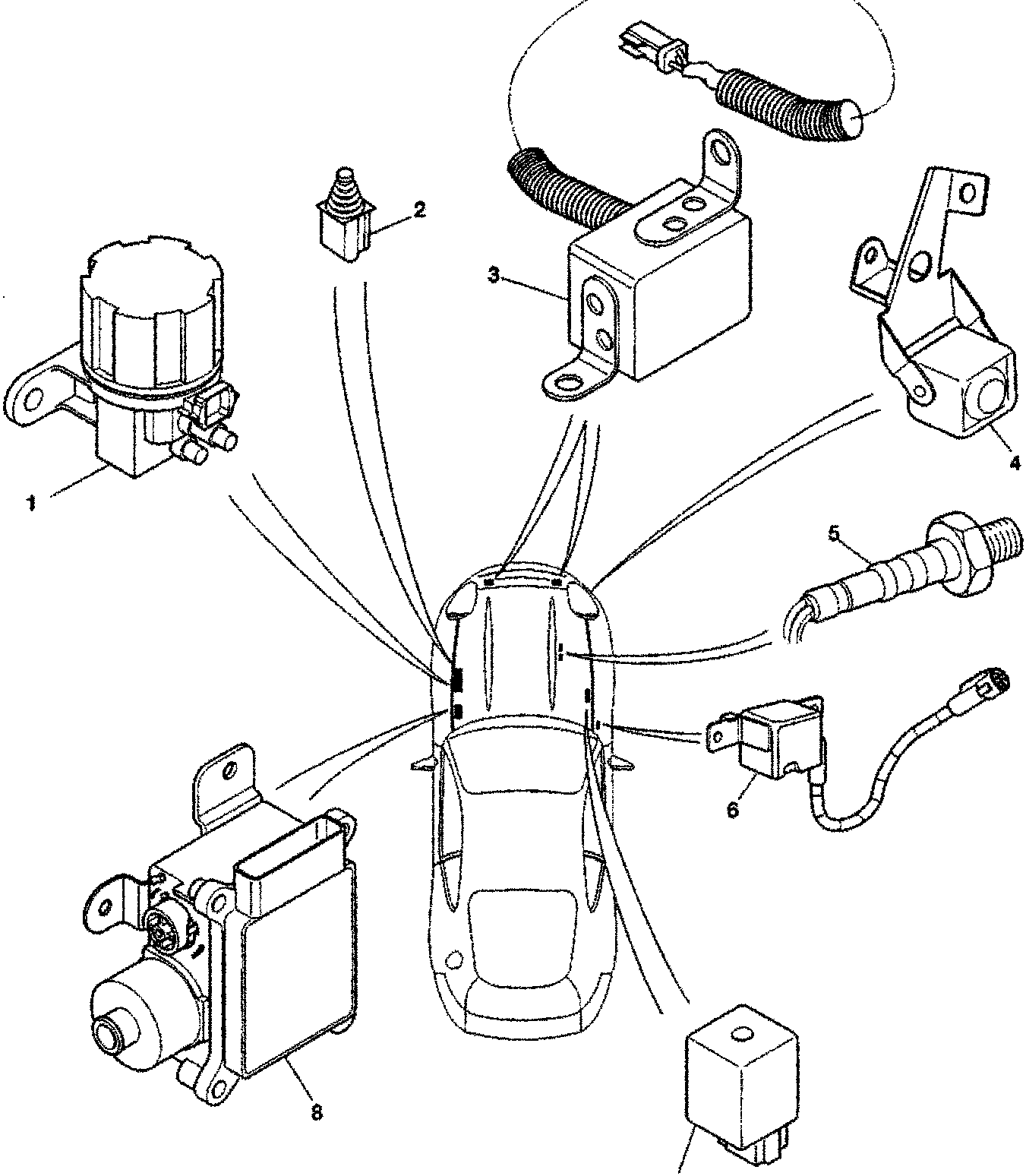
- Sensor assembly with mounting bracket.
- Connector plug.
- Relay module with mounting flange.
- Mounting bracket for sensor unit.
- Throttle position sensor.
- Ignition coil connector.
- Relay module (small).
- Sensor assembly with mounting bracket and gear housing.
Parts & tools for this job For 1994 Aston Martin DB7
- TOOLTorque wrenchSearch: 3/8 inch torque wrench
- TOOLSocket setSearch: socket set metric
- BOOKHaynes manualSearch: Haynes manual Aston Martin DB7
Links open Amazon search results in a new tab. As an Amazon Associate I earn from qualifying purchases.