
Relay Locations (page 2 of 2)
- Make
- Aston Martin
- Model
- DB7 Factory Workshop Manual Volume 2: Electrics, Body and Air Conditioning
- Year
- 1994–1998
- Section
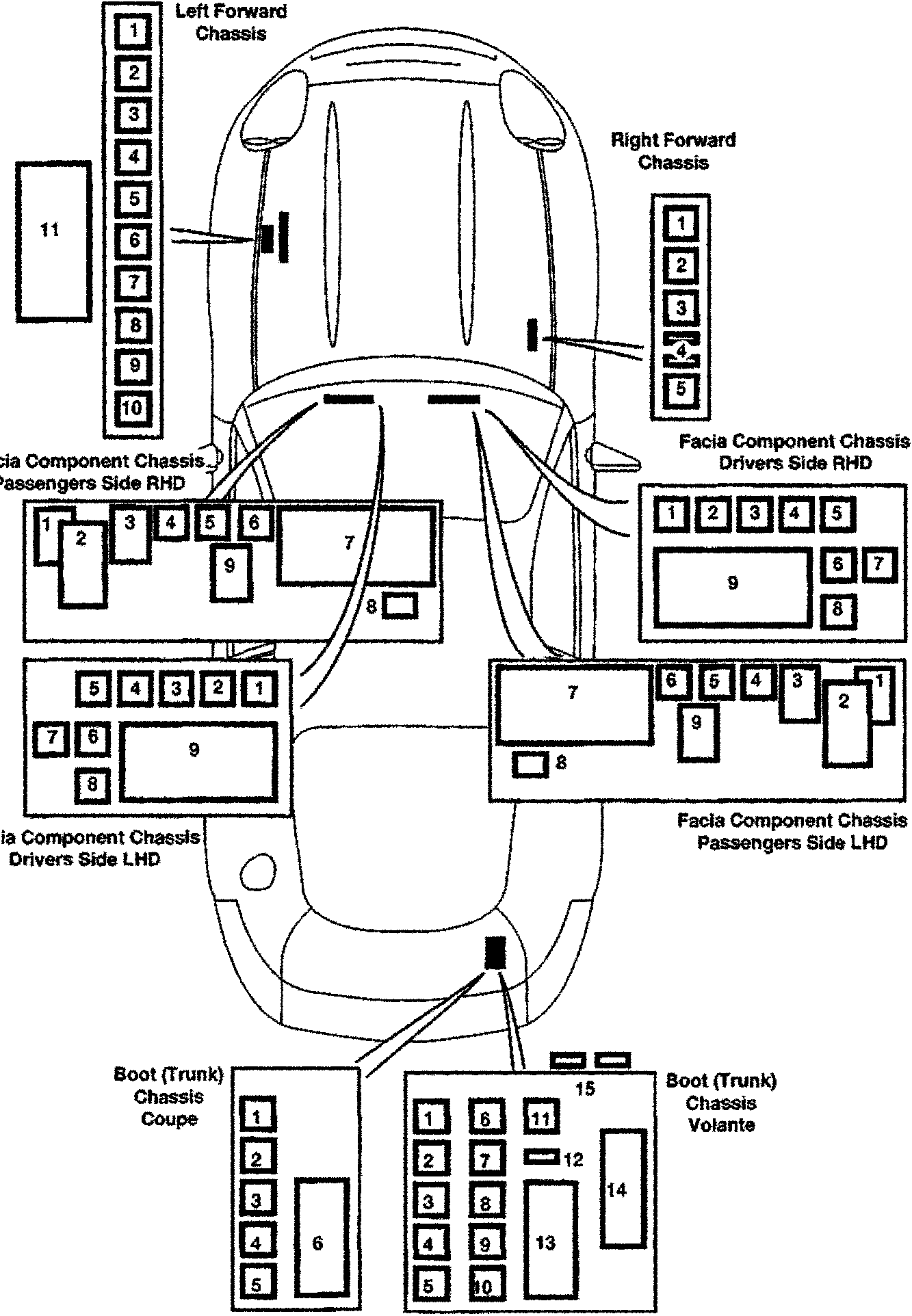
- Relay location diagrams – 97 MY
ElectricsRelay Locations · page 2 of 2
Left Forward Chassis
- 1
- 2
- 3
- 4
- 5
- 6
- 7
- 8
- 9
- 10
Right Forward Chassis
- 1
- 2
- 3
- 4
- 5
Facia Component Chassis Passengers Side RHD
- 1
- 2
- 3
- 4
- 5
- 6
- 7
- 8
- 9
Facia Component Chassis Drivers Side RHD
- 1
- 2
- 3
- 4
- 5
- 6
- 7
- 8
- 9
Facia Component Chassis Drivers Side LHD
- 1
- 2
- 3
- 4
- 5
- 6
- 7
- 8
- 9
Facia Component Chassis Passengers Side LHD
- 1
- 2
- 3
- 4
- 5
- 6
- 7
- 8
- 9
Boot (Trunk) Chassis Coupe
- 1
- 2
- 3
- 4
- 5
- 6
Boot (Trunk) Chassis Volante
- 1
- 2
- 3
- 4
- 5
- 6
- 7
- 8
- 9
- 10
- 11
- 12
- 13
- 14
- 15
Parts & tools for this job For 1994 Aston Martin DB7
- TOOLDigital multimeterSearch: automotive digital multimeter
- PARTAssorted fuse kitSearch: car fuse assortment kit
- TOOLWire crimper and connector kitSearch: wire crimper connector kit
Links open Amazon search results in a new tab. As an Amazon Associate I earn from qualifying purchases.