
060C Warning Lamp Short Circuit
- Make
- Aston Martin
- Model
- DB7 Factory Workshop Manual Volume 2: Electrics, Body and Air Conditioning
- Year
- 1994–1998
- Section
- Seat belt pretensioner system › 060C Warning Lamp Short Circuit
060C Warning Lamp Short Circuit
060C will be logged if the monitor current flow through the SRS/Airbag warning lamp is excessive.
The warning lamp circuit is normally at 12 volts and is switched to ground by the airbag control module or by the pretensioner control module when one of these control modules detects a fault.
If either control module connector is displaced and the ignition is switched on, the warning lamp will be illuminated via the ground shorting link between pins 1 and 2 of the pretensioner controller connector or pins 4 and 5 of the airbag controller connector. both control modules must be checked for the appropriate DTC to isolate which circuit is at fault.
Procedure
- Connect the PDU to the lower diagnostic socket and access the pretensioner control module. Verify that an 060C code is logged and note if the fault is shown as intermittent. Note any other codes in the DTC log and then clear all codes. Go to step 2.
If fault code 060C is not logged, go to the diagnostics section of the airbag system. - Check the security of the pretensioner control module connector.
If the connector is secure, go to step 3.
If the connector is displaced, resecure the connector. Clear all logged DTCs and retest the vehicle to ensure that the problem is resolved. - Access the SRS/Airbag warning lamp and check the lamp resistance.
If the resistance is approximately 120Ω, the lamp is good. Refit the lamp and go to step 4.
If the resistance of the lamp is significantly less than approximately 120Ω, fit a new lamp and refit the instrument panel. Clear the logged DTCs from the pretensioner control module and retest the vehicle to ensure that the problem is resolved. - If the checks in step 3 are good, the low circuit resistance must be in the instrument pack or in the control module. Replace the pretensioner control module and reconnect all components.
- Switch on the ignition and then test the vehicle.
If the 060C code is logged again, replace the instrument pack.
060D Warning lamp open circuit
060D will be logged if the monitor current flow through the SRS/Airbag warning lamp is below the normal monitor level.
The warning lamp circuit is normally at 12 volts and is switched to ground by the airbag control module or by the pretensioner control module when one of these control modules detects a fault.
Procedure
- Connect the PDU to the lower diagnostic socket and access the pretensioner control module. Verify that an 060D code is logged and note if the fault is shown as intermittent. Note any other codes in the DTC log and then clear all codes. Go to step 2.
If fault code 060D is not logged, go to the diagnostics section of the airbag system. - Switch off the ignition. Access the SRS/Airbag warning lamp and check the lamp resistance. The resistance should be approximately 120Ω.
If the resistance is 120Ω, go to step 3.
If the lamp resistance is significantly lower than 120Ω, replace the lamp. Retest the vehicle to ensure that the problem is resolved. - Wait 10 minutes after switching off the ignition to ensure that the pretensioner firing capacitors have fully discharged.
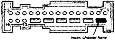
Disconnect the pretensioner control module and temporarily cheat the warning lamp shorting link.
Note: The control module harness connector has a shorting link which short circuits the warning lamp line (pin 2) to ground (pin 1) when the connector is displaced. Carefully insert a suitable non-metallic cheater to remove the short circuit between pins 1 and 2 before continuing with fault diagnosis.
Parts & tools for this job For 1994 Aston Martin DB7
- PARTReplacement bulbsSearch: Aston Martin DB7 1994 bulbs
- TOOLDigital multimeterSearch: automotive digital multimeter
Links open Amazon search results in a new tab. As an Amazon Associate I earn from qualifying purchases.