
Description
- Make
- Aston Martin
- Model
- DB9 Factory Workshop Manual
- Year
- Issue 2, 2005
- Section
- Valve Train › Description
Description
Camshafts
Inlet and exhaust camshafts in each head are chain driven directly from the crankshaft.
The twin crankshaft sprocket has 18 teeth and each camshaft sprocket has 36 teeth, the timing chains have 61 links. Three chain links are marked and are aligned with timing marks on the crankshaft and camshaft sprockets during valve timing. Because of the odd number of links in the timing chains, the timing marks and marked links will only align once every 122 engine revolutions.
Specifications
| Valves, Guides & Springs | Nm. |
|---|---|
| Spring Force at 40mm Spring Height | 290 |
| MM | |
|---|---|
| Installed Spring Height (Exhaust / Inlet) | 39.69-40.29 |
| Valve Guide Internal Diameter | 6.015 - 6.044 |
| Valve Guide Maximum Runout | 0.030 |
| Valve Stem Diameter - Inlet | 5.975 - 5.995 |
| Valve Stem Diameter - Exhaust | 5.950 - 5.970 |
| Valve Stem Clearance - Inlet | 0.020-0.069 |
| Valve Stem Clearance - Exhaust | 0.046-0.095 |
| Valve Face Maximum Runout | 0.050 |
| Valve Lash Adjusters | |
|---|---|
| Bore | 15.018 - 16.057 |
| Outside Diameter | 15.988 - 16.000 |
| Clearance | 0.018 - 0.069 |
| Torque Figures | ||
|---|---|---|
| Description | Nm | lb. / ft. |
| Timing chain guide | 20-30 | 15-22.5 |
| Tensioners | 20-30 | 15-22.5 |
| Timing cover bolts | 23-27 | 17-20 |
Maintenance
Valve Timing Chains
| Repair Operation Time (ROT) | |
|---|---|
| Item | Code |
| Timing Chain Renew | TBA |
Removal
- Remove the engine from the vehicle (Refer to 'Engine', page 3-1-4).
- Remove the camshaft covers (Refer to 'Camshaft Cover', page 3-11-1)
- Remove the timing cover (Refer to 'Timing Cover', page 3-11-3).
- Remove the crankshaft timing disc.
Note the orientation of the disc for installation.
Image to Follow
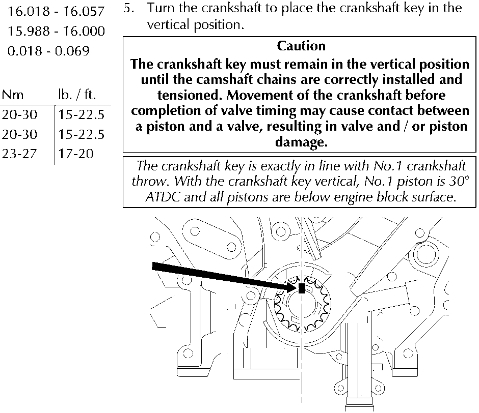
- Turn the crankshaft to place the crankshaft key in the vertical position.
Caution
The crankshaft key must remain in the vertical position until the camshaft chains are correctly installed and tensioned. Movement of the crankshaft before completion of valve timing may cause contact between a piston and a valve, resulting in valve and / or piston damage.
The crankshaft key is exactly in line with No.1 crankshaft throw. With the crankshaft key vertical, No.1 piston is 30° ATDC and all pistons are below engine block surface.
Parts & tools for this job For 2005 Aston Martin DB9
- PARTEngine gasket setSearch: Aston Martin DB9 2005 engine gasket set
- TOOLTorque wrenchSearch: 3/8 inch torque wrench
- TOOLFeeler gauge setSearch: feeler gauge set
Links open Amazon search results in a new tab. As an Amazon Associate I earn from qualifying purchases.