
Shock Absorber System: Specifications
- Make
- Aston Martin
- Model
- DB9 Factory Workshop Manual
- Year
- Issue 2, 2005
- Section
- Shock Absorber System › Specifications
Movement of each road spring is independently damped by a telescopic, hydraulically-controlled shock absorber. Each shock absorber is installed coaxially within the road spring. Front spring and damper assemblies are located between the upper suspension arm and attach to the lower suspension arm and the body structure.
Rear spring and damper assemblies attach to the lower suspension arm and the rear subframe, via a mounting bracket, laying to the rear of the upper suspension arm.
Specifications
| Torque Figures | ||
|---|---|---|
| Description | Nm | lb. / ft. |
| Front | ||
| Spring and Damper Top Mounts | 22.5 | 17 |
| Spring and Damper Bottom Mount | 175 | 129.5 |
| Upper Suspension Arm | 115 | 85 |
| Rear | ||
| Spring and Damper Bracket Mounting | 75-80 | 55.5-59.5 |
| Spring and Damper Top Mounting to Bracket | 22.5 | 17 |
| Spring and Damper Lower Mounting | 175 | 129.5 |
| Vertical Link to Lower Suspension Arm | 175 | 129.5 |
| Track-rod Arm to Lower Suspension Arm | 115 | 85 |
Maintenance (Front)
Spring and Damper Assembly
| Repair Operation Time (ROT) | |
|---|---|
| Item | Code |
| Spring and Damper Unit Renew | (LH) 04.03.AB (RH) 04.03.BB |
Removal
- Raise the vehicle and make safe.
- For each affected wheel station remove the road wheel(s).
- Disconnect the ABS sensor wiring harness plug.
- Remove the upper suspension arm from the body structure.
Allow the upper suspension arm and the Vertical link to fall back, giving access to the spring and damper assembly.
Caution
Ensure the brake flex hose is not over stretched.
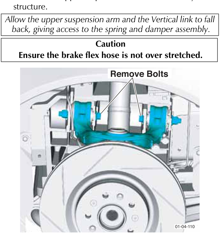
Ensure the spring and damper assembly is fully extended.
- Remove the spring and damper top mount nuts (x3).
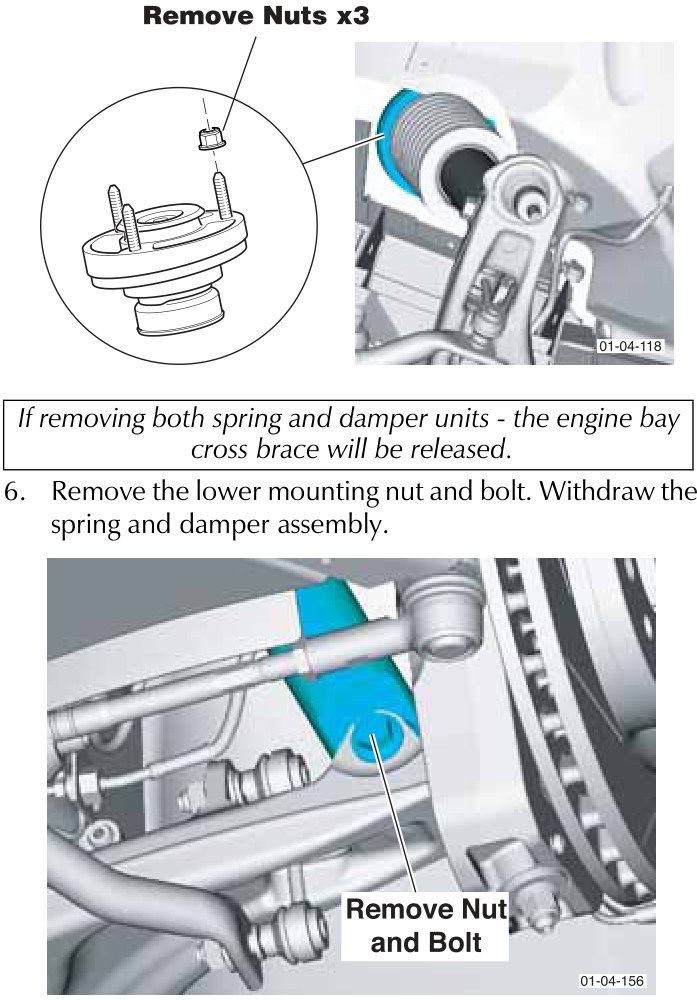
If removing both spring and damper units - the engine bay cross brace will be released.
- Remove the lower mounting nut and bolt. Withdraw the spring and damper assembly.
Parts & tools for this job For 2005 Aston Martin DB9
- TOOLCoil spring compressorSearch: coil spring compressor
- TOOLBall joint separatorSearch: ball joint separator
- PARTShock absorbersSearch: Aston Martin DB9 2005 shock absorbers
Links open Amazon search results in a new tab. As an Amazon Associate I earn from qualifying purchases.