
Description
- Make
- Aston Martin
- Model
- V8 Vantage Factory Workshop Manual
- Year
- 2005–2010
- Section
- Front Suspension › Description
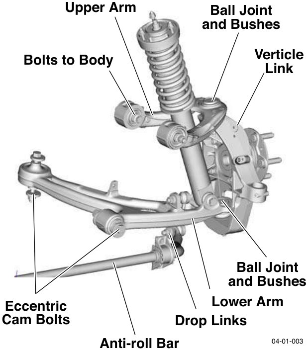
Description
Suspension Arms
The upper suspension arm is attached to the body structure. The lower suspension arm is attached to the front subframe. Each upper suspension arm has a press-fit ball-joint, and two interleaved rubber bushes. Two bolts attach the upper suspension arm to the body structure. Each lower suspension arm has a press fit ball-joint and metal-to-rubber bonded bushes which are attached to the front subframe by two eccentric cam bolts (Camber and castor settings).
Anti-roll Bar
The anti-roll bar, is attached to the subframe in two positions by rubber bushes and clamps. The outer ends of the anti-roll bar are attached to the lower suspension arms by drop links. The anti-roll bar provides the required stiffness to control body roll.
Vertical link
The Vertical link (Knuckle Joint) swivels on the upper and lower suspension arms via ball-joints, and carries the hub, a unit 3 wheel bearing (including the ABS encoder ring), the wheel speed sensor, the brake caliper, and the brake disc and shield. The position of the Vertical link is determined by the movement of the steering rack, which is connected to the Vertical link by the steering track rod.
Specifications
Torque Figures
| Description | Nm | lb. / ft. |
|---|---|---|
| Brake dust shield. | 9 | 7 |
| Bearing Assembly to the Vertical link. | 55 | 41 |
| Vertical Link to the Lower Suspension Arm. | 90 | 66.5 |
| Vertical Link to the Upper Suspension Arm. | 90 | 66.5 |
| Track-rod End Lock Nut. | 70 | 52 |
| Vehicle Ride Height Sensor. | M8 22.5 | 17 |
| M5 9 | 7 | |
| Anti-roll Bar Link Nuts | 110 | 81.5 |
| Anti-roll Bar Mounting Bolts | 22.5 | 17 |
| Torque bolt 1, then bolt 2, then bolt 1 again (to allow for rubber compression) |
Torque the following suspension fixings with the vehicle at normal ride height
| Fixing | Metric | Imperial |
|---|---|---|
| Lower Suspension Arm front bush to the Subframe | M14 185 | 137 |
| Lower Suspension Arm rear bush to the Subframe. | M12 115 | 85 |
| Upper Suspension Arm to the Front Structure | 115 | 85 |
| Spring and Damper Bolts | Top 22.5 | 17 |
| Lower 175 | 129.5 |
Normal ride height
2 x 37.5kg in front seats (37.5kg in each seat) plus a full fuel tank.
Parts & tools for this job For 2005 Aston Martin V8 Vantage
- TOOLCoil spring compressorSearch: coil spring compressor
- TOOLBall joint separatorSearch: ball joint separator
- PARTFront shock absorbersSearch: Aston Martin V8 Vantage 2005 front shock absorbers
Links open Amazon search results in a new tab. As an Amazon Associate I earn from qualifying purchases.