
A2
| Removing and installing cylinder head |
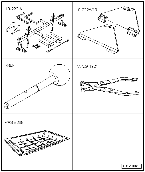
| Special tools and workshop equipment required |
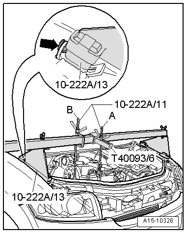
| t | Support bracket -10 - 222 A- |
| t | Adapter -10 - 222 A /13- |
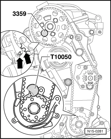
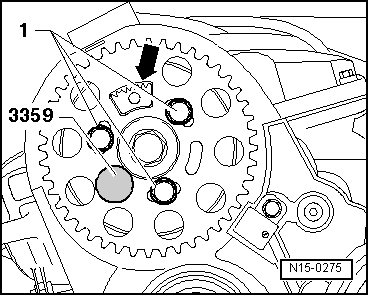
| t | Diesel injection pump locking pin -3359- |
| t | Hose clip pliers -V.A.G 1921- |
| t | Drip tray for workshop hoist -VAS 6208- |
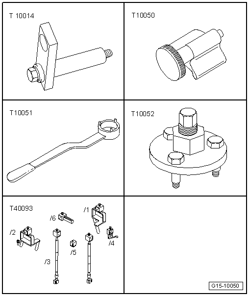
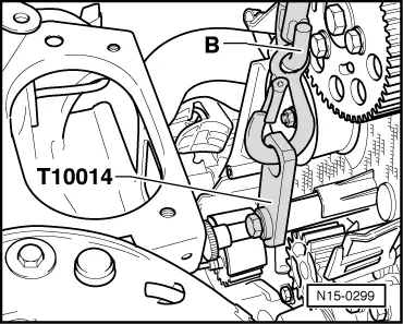
| t | Bracket -T10014- |
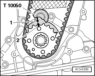
| t | Crankshaft stop -T10050- |
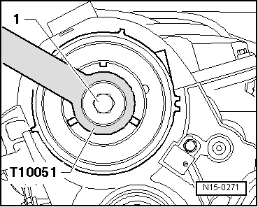
| t | Counterhold tool -T10051- |
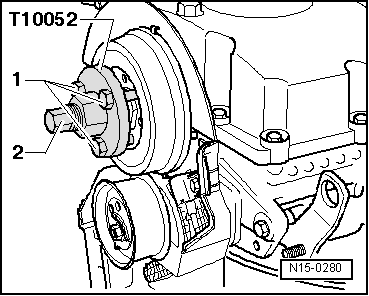
| t | Puller -T10052- |
| t | Adapter -T40093/6- from engine support bracket (supplementary set) -T40093- |
 Note
Note
|
 Caution
|
|
|
|
Note
|
|
Note
|
|
|
|
Note
|
|
Note
|
|
|
|
Note
|
|
|
|
|
|
Note
|
|
Note
|
|
|
|
|
|
|
|
 WARNING
|
|
|
|
|
|
|
|
|
|
|
|
|
|
Note
|
|
Note
|
|
|
|
|
|
|
|
|
|
|
|
|
|
|
|
Note
|
|
|
|
|
|
Note
|
|
|
|
|
|
Note
|

|
Note
|
|
Note
|
|
|
|
|
|
|
|
|
|
|
|
|
|
Note
|
|
Note
|
|
|
|
|
|
Note
|
|
Note
|
|
|
|
|
|
Note
|
|
| Component | Nm | ||||
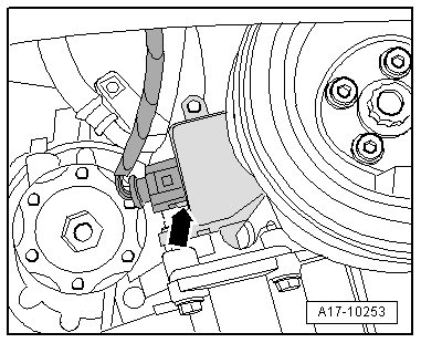
| Hall sender -G40- to cylinder head | 10 1) | ||||
| Rear toothed belt cover to cylinder head | M6 | 10 1) | |||
| M8 | 20 1) | ||||
| Stud to cylinder head | 15 | ||||
| Hub to camshaft | 100 | ||||
| Engine support to cylinder block | 45 | ||||
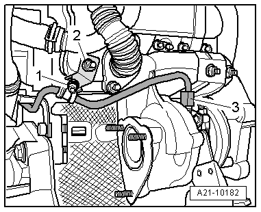
| Oil supply pipe to: | Oil filter bracket | 22 | |||
| Turbocharger | 22 | ||||
| Oil return pipe to: | Turbocharger | 15 | |||
| Cylinder block | 30 | ||||
| Support for turbocharger to: | Turbocharger | 20 | |||
| Cylinder block | 25 | ||||
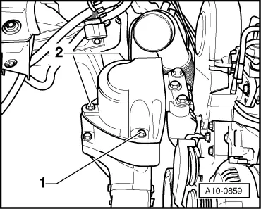
| Bracket for wiring harness to coolant hose/pipe connection | 10 | ||||
| Bracket for oil supply pipe to coolant hose/pipe connection | 10 | ||||
| Air pipe to: | Turbocharger | 8 | |||
| Sump | 8 | ||||
| Drive shaft heat shield to cylinder block | 33 | ||||
| Engine cover panel to bracket | 5.5 | ||||
| |||||