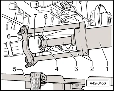
| The illustration shows the set-up for removing the bush on the left side of the rear axle. |
| –
| Set up special tools on rear axle as illustrated. |
| –
| Wrap a plastic bag over the special tools and axle beam to catch escaping fluid immediately when the bush is pressed out. |
| –
| Press out centre core of bonded rubber bush. |
| 1 - | Hydraulic press -VAS 6178- |
| 2 - | Cylinder attachment with pull rods -VAS 6180/1- |
| 3 - | Extension (long) -VAS 6180/4- |
| 4 - | Thrust piece (nominal diameter 12 mm) -VAS 6180/3- |
| 5 - | Engine and gearbox jack -V.A.G 1383 A- |
| 6 - | Splitter -VAS 6180/2- |
| 8 - | Hydraulic bonded rubber bush |

Note! | t
| Jaws of splitter -VAS 6180/2- must be positioned between collar on bonded rubber bush and eye of trailing arm. |
| t
| “Top” marking on splitter -VAS 6180/2- must face outer left side of vehicle when pressing out left bonded rubber bush, and outer right side of vehicle when pressing out right bush. |
| Pressing out sleeve of hydraulic bonded rubber bush |
|
|
|