audi Workshop Repair Guides

Audi Workshop Service and Repair Manuals

Installing > < Notes for working on power steering box
Removing
Removing
–  Disconnect battery → Electrical system; Rep. Gr.27.
  Caution
Turn steering wheel to centre position (wheels straight-ahead) and do not turn while performing repair work, as otherwise coil connector of airbag module could be damaged.
   
–  To prevent unintentional turning, secure steering wheel in straight-ahead position with adhesive tape -arrow-.
  Note!
Only use adhesive tape that can be completely removed from the steering wheel afterwards without leaving marks.
  A48-0346
–  Remove bolt -1-.
–  Pull cover -2- to the left and disengage.
–  Remove floor mat on driver's side → General body repairs, interior; Rep. Gr.70.
  A48-0329
–  Remove hexagon bolt -1-.
–  Pull universal joint off steering box.
–  Remove front wheels.
–  Remove noise insulation → General body repairs, exterior; Rep. Gr.50.
–  Remove front left wheel housing liner → General body repairs, exterior; Rep. Gr.66.
–  Loosen nut on swivel joint.
  A48-0338
–  Apply ball joint puller -3287 A--1- as shown in the illustration and press out swivel joint.
  Note!
t  Take care not to damage rubber boot when inserting ball joint puller.
t  Leave nut screwed several turns onto track rod ball joint to protect thread.
  A40-0334
–  Detach track rods from steering arms using ball joint puller -Kukko 129/1--1-.
  Note!
Take care not to damage rubber boot when inserting ball joint puller.
–  Unscrew nut from track rod ball joint.
–  Place drip tray under motor/pump unit to collect escaping hydraulic fluid.
  A48-0347
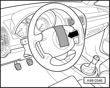
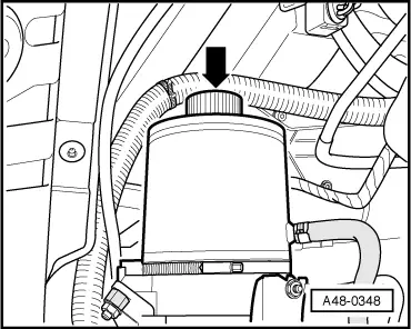
–  Remove screw cap -arrow- from fluid reservoir of motor/pump unit.
–  Extract hydraulic fluid via the filler neck with a commercially available extractor bottle.
  Note!
t  Small quantities of hydraulic fluid will remain in the motor/pump unit as well as in the return line and expansion hose after extraction.
t  Do not re-use hydraulic fluid which has been drained off.
t  The expansion hose and return line must not be clamped with hose clamps, e.g. -3094- or other tools. Clamping can cause damage to the expansion hose and return line.
t  To avoid damage, a bending radius of less than 100 mm is not permissible when bending or suspending the expansion hose and return line.
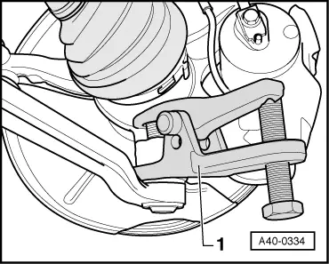
–  Place drip tray under steering box to collect escaping hydraulic fluid.
  A48-0348
–  Unbolt steering box from subframe -arrows-.
–  Locate subframe → Chapter.
  Note!
When lowering subframe, ensure that the expansion hose, return line and wiring from power steering sensor -G250- are not under tension.
  A40-0348
–  Disconnect expansion hose -1- and return line -2- from steering box and seal off with a plastic bag and adhesive tape.
–  Tie up expansion hose and return line.
–  Seal tapped holes on steering box (e.g. with plastic screw plugs).
–  Unscrew socket-head bolts -4-.
–  If fitted, remove power steering sensor-3- from steering box.
–  Lower subframe -5- with engine and gearbox jack -V.A.G 1383A-.
–  Take out steering box towards the rear.
  A48-0349

Installing > < Notes for working on power steering box