A3 Mk1
|
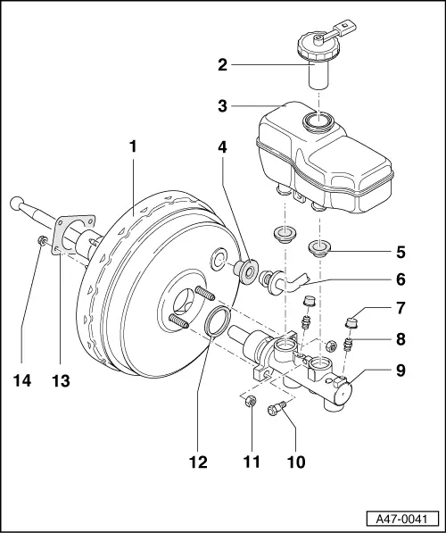
Brake servo/brake master cylinder - RHD
Exploded view
Note: Brake master cylinder and brake servo assemblies can be replaced separately.
|
 |
|
|
|
|
|
|
|
|

|
Brake servo/brake master cylinder - RHD
Exploded view
Note: Brake master cylinder and brake servo assemblies can be replaced separately.
|
|
|
|
|
|
|
|
|
|