audi Workshop Repair Guides

Audi Workshop Service and Repair Manuals

Removing and installing overheating fuse S24 / overheating sensor G189 and temperature sensor G18 > < Assembling burner housing with heat exchanger and outer casing
Assembling auxiliary heater control unitJ364 and burner element
Assembling auxiliary heater control unit -J364- and burner element
  Note
   
t  Depending on the version of the auxiliary heater design (with or without fuel shut-off valve -N109--A-), different versions of the auxiliary heater control unit -J364--C- and the metering pump -V54- are fitted → Chapter and → Electronic parts catalogue.
t  The installation of a fuel shut-off valve -N109--A- in the fuel line of the burner element -B- is currently only planned for vehicles with diesel engine (only installed on VW vehicles; introduction for Audi vehicles not yet finalised) → Electronic parts catalogue.
t  Currently no auxiliary heater with a fuel shut-off valve -N109--A- is installed in Audi A3 vehicles during production (introduction not yet finalised). However it is possible that individual vehicles have been retro-fitted with an auxiliary heater with a fuel shut-off valve -N109-; therefore it is important to pay attention to the correct version.
  A82-10073
t  Prior to assembly, remove any combustion residue from or out of burner element -B- .
t  Pay attention to correct assignment of auxiliary heater control unit -J364--A- and burner element -B- (different versions).
t  This illustration shows burner element for diesel (with wiring and connector for fuel pre-heating heater element -Z66-).
t  If burner element is defective, glow plug with flame monitor -Q8- must also be renewed (currently not available as a separate replacement part) → Electronic parts catalogue.
t  Renew burner element if deposits have formed which affect heating operation and cannot be removed with workshop equipment.
  A82-0491
t  
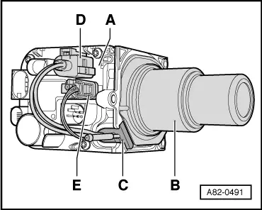
Version for petrol (without wiring and connector for fuel pre-heating heater element -Z66-) features a connector -E- with no wiring (to stop ingress of dirt and moisture into control unit via connection).
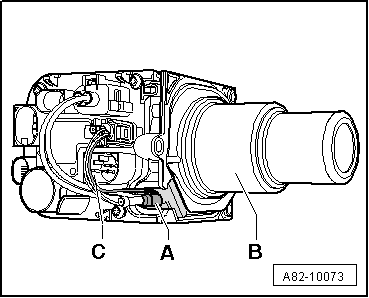
–  Assemble auxiliary heater control unit -J364- (with combustion air blower) -A- and burner element -B- as shown, paying particular attention to correct installation position of grommet -C-.
–  Plug in connectors -D- (to glow plug with flame monitor -Q8-) and -E- (to fuel pre-heating heater element -Z66-, diesel version only) at control unit.
  A82-0491

Removing and installing overheating fuse S24 / overheating sensor G189 and temperature sensor G18 > < Assembling burner housing with heat exchanger and outer casing