| –
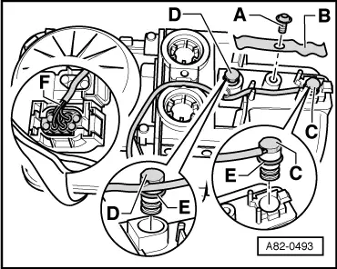
| Remove bolt -A- and detach clip -B-. |
| –
| Carefully pull the overheating fuse -S24- / overheating sensor -G189--Item C- and the temperature sensor -G18--D- out of the auxiliary heater (e.g. by applying gripping pliers directly to the housing). In doing so, take care not to damage components which are to be re-used. |
| –
| Unplug connector -F- from auxiliary heater control unit -J364-. |
| –
| Check and clean both openings in the outer casing of the auxiliary heater into which the temperature sensor -G18--D- and the overheating fuse -S24- / overheating sensor -G189--C- are inserted. Also check the contact surfaces at the heat exchanger for these components (via the two openings in the auxiliary heater). |
| –
| Attach one new O-ring -E- to theoverheating fuse -S24- / overheating sensor -G189--C- and the temperature sensor -G18--D- |
| –
| Before installing, lubricate both O-rings -E-, e.g. with coolant. |
| –
| Insert overheating fuse -S24- / overheating sensor -G189--C- and temperature sensor -G18--D-. |
|
|
|
 Note
Note