
A3 Mk2
|
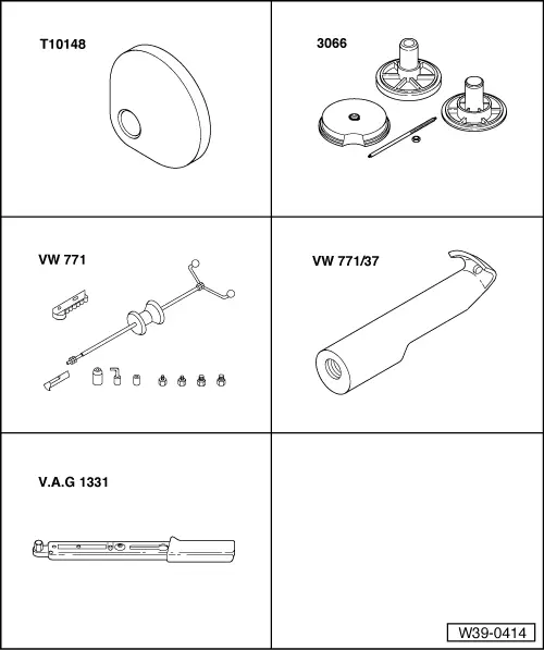
| Special tools and workshop equipment required |
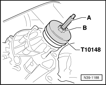
| t | Thrust piece -T10148- |
| t | Spindle from assembly device -3066- |
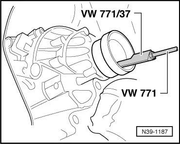
| t | Multi-purpose tool -VW 771- |
| t | Puller hook -VW 771/37- |
| t | Torque wrench -V.A.G 1331- |
|
|
|
|
|
|
|
|
|
|
|
|
|
|
|
|
|
|
|
|
|
|
|
|
|
|
|
|
|
|
|
|
|
|
| Component | Nm | |
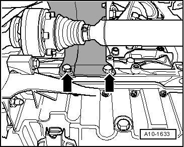
| Heat shield for drive shaft to cylinder block, M10 | 40 | |