audi Workshop Repair Guides

Audi Workshop Service and Repair Manuals

Overview - gear oil in bevel box > < Removing bevel box - vehicles with diesel engine
Installing bevel box
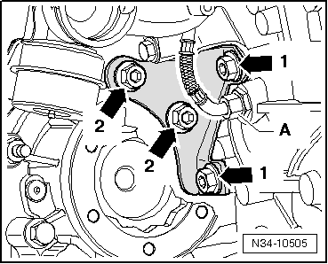
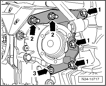
Installation is carried out in reverse sequence; note the following:
t  
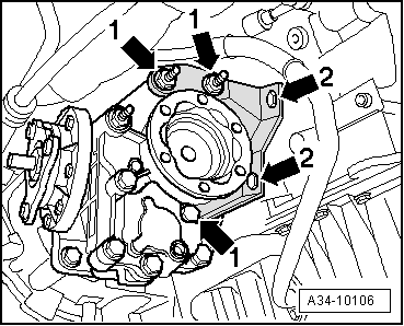
Renew gaskets, seals and self-locking nuts.
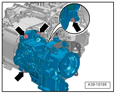
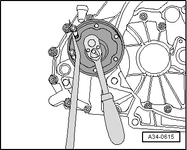
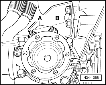
–  Push bevel box fully onto gearbox, ensuring that splines of bevel box input shaft and differential are centred when brought together.
–  Also align the teeth of the flange shaft (right-side) and the differential pinion; if necessary turn the flange shaft.
–  If the teeth are correctly positioned and the components are located centrally, the bevel box will slide against the gearbox onto the stop.
   
–  Secure bevel box to gearbox -arrows-. Tightening torque → 
  Note
Do not use the securing bolts to pull the bevel box onto the gearbox. This could cause the bevel box to tilt and the securing eyes could break off.
  A39-10189
–  Install gearbox carrier -A-. Note the correct assembly sequence → Anchor.
  N34-10718
Vehicles with diesel engine and particulate filter:
–  Install bracket for turbocharger. To do so, tighten bolt -2- and banjo bolt -3- → Rep. Gr.21.
–  Install bracket for particulate filter → Rep. Gr.26.
  A21-10088
–  Install flange shaft (right-side) → Anchor.
Continued for all vehicles:
  A37-0675
–  Tighten bolt for flange shaft (right-side) -arrow 1- using socket and extended bit -T10107 A-.
–  Install drive shaft (right-side) → Rep. Gr.40.
–  Install subframe → Rep. Gr.40.
–  Attach steering box to subframe → Rep. Gr.48.
–  Press engine/gearbox assembly towards bulkhead, taking care to guide pin on bevel box into propshaft flange.
  Note
t  When removing and installing the bevel box do not damage the seal in the propshaft flange. Renew propshaft if damaged.
t  Ensure propshaft is horizontal when pushing it onto centring pin.
  A34-0615
–  Secure pendulum support to gearbox with bolts -2- and -3- (use new bolts → Item).
–  Bolt flexible coupling on propshaft onto bevel box flange → Rear final drive 02D, 0AV, 0BR and 0BY; Rep. Gr.39.
–  If previously removed, install front left vehicle level sender -G78-.
–  Assemble exhaust system and install all exhaust system brackets → Rep. Gr.26.
–  Check oil level in bevel box → Chapter.
–  Check gear oil level in manual gearbox and top up as required → Chapter.
–  Install noise insulation → Rep. Gr.66.
–  Fit wheels → Rep. Gr.44.
  A10-1578
Heat shield for drive shaft (right-side)
–  Tighten bolts -arrows- to 20 Nm.
  A39-0277
Assembly sequence: securing gearbox carrier for bevel box to engine and bevel box
Vehicles with TFSI engine:
–  Screw in bolts -arrows 1- (hand-tight).
–  Tighten bolts -arrows 2- → Item.
–  Tighten bolts -arrows 1- → Item.
  A34-10106
Vehicles with V6 engine:
–  Screw in bolts -A- (hand-tight).
–  Tighten bolts -B- → Item.
–  Tighten bolts -A- → Item.
  N34-1068
Vehicles with TDI engine without particulate filter
–  Screw in bolts -arrows 1- (hand-tight).
–  Tighten bolts -arrows 2- → Item.
–  Tighten bolts -arrows 1- → Item.
  N34-10505
Vehicles with TDI engine with particulate filter
Allocation of bolts:
  N34-10717
ItemBoltQty.
1M10 x 213
2M10 x 45
t  The bolt head was modified to match the head of the other bolts shortly after start of production
2
3M10 x 621

–  Screw in all bolts hand-tight.
–  Tighten bolts -arrows 2- and -arrow 3- → Item.
–  Tighten bolts -arrows 1- → Item.
   

Overview - gear oil in bevel box > < Removing bevel box - vehicles with diesel engine