
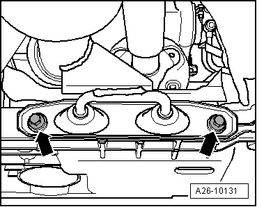
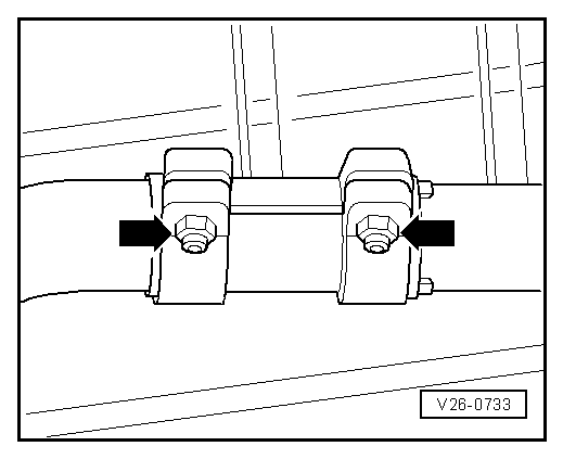
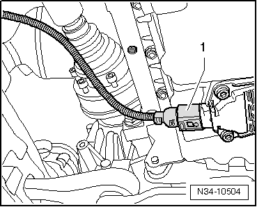
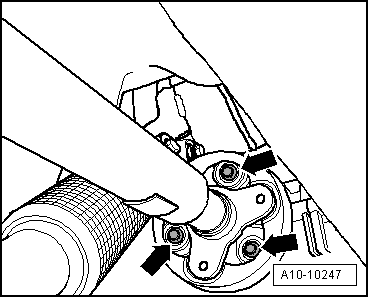
A3 Mk2
| Removing gearbox - vehicles with TDI engine |

| Special tools and workshop equipment required |
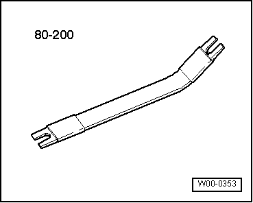
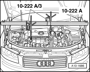
| t | Support bracket -10 - 222 A- |
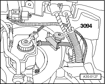
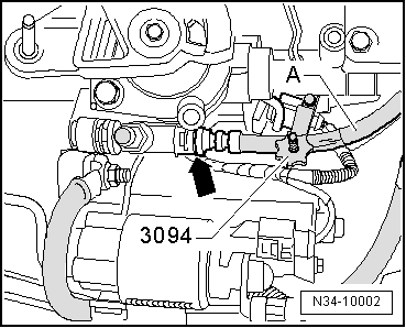
| t | Hose clamps, up to 25 mm -3094- |
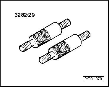
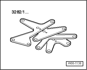
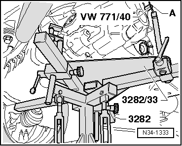
| t | Gearbox support -3282- |
| t | Adapter -VW 771/40- |
| t | Engine and gearbox jack -V.A.G 1383 A- |
|
|
|
|
|
|
|
|
|
|
 Note
Note
|
|
 Caution
|
|
|
|
|
|
|
|
|
|
|
|
|
|
|
|
|
|
|
|
Note
|
|
|
|
Note
Note |
|
Note
|
|
|
|
|
|
|
|
|
|
|
|
|
|
|
|
|
|
|
|
|
|
Note
|
|
|
|
|
|
|
|
Note
|
|
|
|
|
|
|
|
|
|
Note
|
|
|
|
|
|
|
|
|
|
|
|
Note
|
|
Note
|

|
|
|
|
|
|
|
Note
|
|