
A3 Mk2
| Dismantling and assembling input shaft |
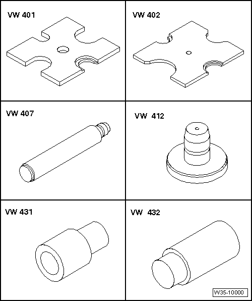
| Special tools and workshop equipment required |
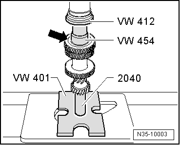
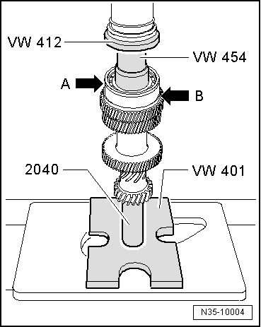
| t | Thrust plate -VW 401- |
| t | Thrust plate -VW 402- |
| t | Press tool -VW 407- |
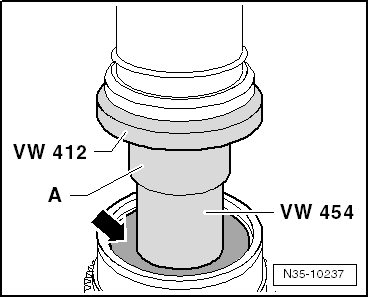
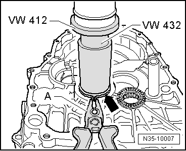
| t | Press tool -VW 412- |
| t | Press tool -VW 431- |
| t | Press tool -VW 432- |
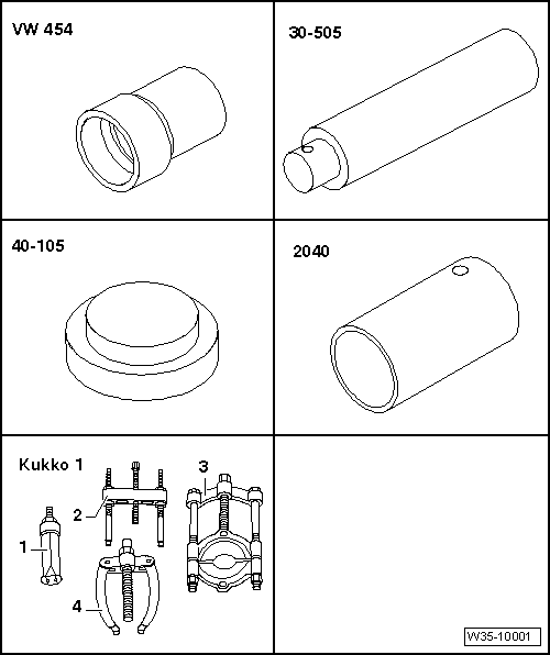
| t | Press tool -VW 454- |
| t | Mandrel -30 - 505- |
| t | Thrust plate -40 - 105- |
| t | Tube -2040- |
| t | -1- Kukko internal puller 21/5 |
| t | -2- Puller 18/1 |
| t | -3- Splitter 17/1 and 17/2 |
| t | -4- Kukko 22/2 counter-support |
|
|
|
|
|
|
|
|
|
|
| Measured value (mm) | Circlip thickness (mm) | Axial clearance (mm) |
| 0.01 … 0.05 | 1.86 | 0.01 … 0.05 |
| 0.05 … 0.07 | 1.89 | 0.01 … 0.05 |
| 0.07 … 0.10 | 1.92 | 0.01 … 0.05 |
| 0.10 … 0.13 | 1.95 | 0.01 … 0.05 |
| 0.13 … 0.16 | 1.98 | 0.01 … 0.05 |
|
|
|
|