
A3 Mk2
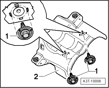
| Removing and installing flexible coupling (rear) |
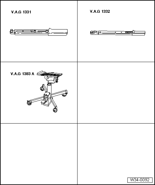
| Special tools and workshop equipment required |
| t | Torque wrench -V.A.G 1331- |
| t | Torque wrench -V.A.G 1332- |
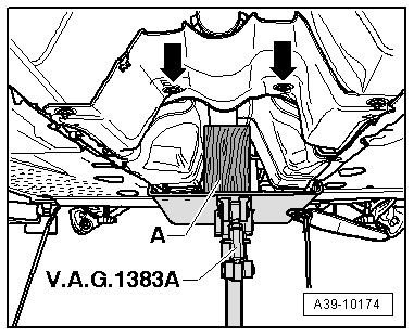
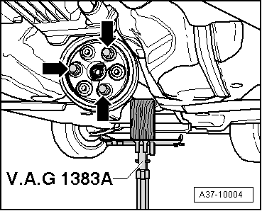
| t | Engine and gearbox jack -V.A.G 1383 A- with universal gearbox support -V.A.G 1359/2- |
|
 Note
Note
|
|
|
|
 Caution
|
|
|
|
|
|
|
|
|
|
Note
|
|
|
|
Note
|
|
|
|
|
|
|
|
|
|
|
|
|
|