A3 Mk2
| Exhaust gas temperature control - exploded view |

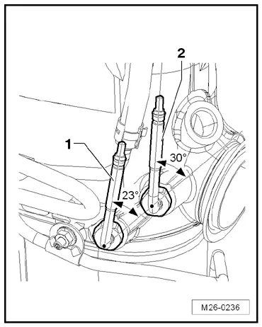
| 1 - | Bolt |
| q | Tightening torque → Rep. gr.23 |
| 2 - | Bolt |
| q | Tightening torque → Rep. gr.23 |
| 3 - | Pressure differential sender -G505- |
| q | Removing and installing → Rep. gr.23 |
| 4 - | Control pipe |
| q | Control pipe from exhaust gas recirculation cooler to exhaust gas pressure sensor 1 |
| 5 - | Exhaust gas pressure sensor 1 -G450- |
| q | Removing and installing → Rep. gr.23 |
| 6 - | Bolt |
| q | Tightening torque → Rep. gr.23 |
| 7 - | Bolt |
| q | Tightening torque → Rep. gr.23 |
| 8 - | Exhaust gas temperature sender 3 -G495- |
| q | 45 Nm |
| q | Removing and installing → Chapter |
| q | Note installation position → Fig. |
| q | Coat with high-temperature paste; for high-temperature paste refer to → Electronic parts catalogue |
| 9 - | Exhaust gas temperature sender 2 -G448- |
| q | 45 Nm |
| q | Removing and installing → Chapter |
| q | Note installation position → Fig. |
| q | Coat with high-temperature paste; for high-temperature paste refer to → Electronic parts catalogue |
| 10 - | Exhaust gas temperature sender 1 -G235- |
| q | 45 Nm |
| q | Before removing mark installation position |
| q | Removing and installing → Chapter |
| q | Coat with high-temperature paste; for high-temperature paste refer to → Electronic parts catalogue |
| 11 - | Turbocharger |
| 12 - | Lambda probe -G39- with Lambda probe heater -Z19- |
| q | Removing and installing → Rep. gr.23 |
| 13 - | Exhaust gas temperature sender 4 -G648- |
| q | 45 Nm |
| q | Removing and installing → Chapter |
| q | Before removing mark installation position |
| q | Coat with high-temperature paste; for high-temperature paste refer to → Electronic parts catalogue |
| q | Routing of wire → Chapter |
| 14 - | Particulate filter |
| 15 - | Lambda probe after catalytic converter -G130- |
| q | Removing and installing → Rep. gr.23 |
| q | Routing of wire → Chapter |
| 16 - | NOx storage catalytic converter |
| 17 - | Clamp |
| 18 - | Seal |
| 19 - | Control pipe |
| q | Tightening torque → Rep. gr.23 |
| q | Do not attempt to bend control pipe to a different shape |
| q | Install free of stress |
| 20 - | Nut |
| q | 9 Nm |
| 21 - | Bracket |
| q | For control pipe |
| 22 - | Bracket |
| q | For pressure differential sender -G505- |
| 23 - | Bolt |
| q | Tightening torque → Rep. gr.23 |
| 24 - | Bracket |