Audi Workshop Service and Repair Manuals
HOME
FEATURES
MENU
INDEX
ABOUT US
Removing and installing exhaust gas temperature sender 2G448 >
< Exhaust gas temperature control - exploded view
A3 Mk2
Power unit
4-cylinder TDI engine (2.0 ltr. 4-valve common rail), mechanics
Exhaust system
Exhaust gas temperature control (vehicles with engine code CBEA)
Removing and installing exhaust gas temperature sender 1G235
Removing and installing exhaust gas temperature sender 1G235
Removing and installing exhaust gas temperature sender 1 -G235-
Special tools and workshop equipment required
t
Crow foot wrench (commercially available)
Removing
–
Remove filter
→ Chapter
.
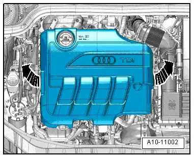
–
Remove engine cover panel
-arrows-
.
–
Unplug electrical connector
-3-
for exhaust gas temperature sender 1 -G235- and move electrical wiring clear.
Note
Disregard
-items 1, 2, 4 and 5-
.
–
Remove bolt
-1-
.
–
Mark installation position of exhaust gas temperature sender 1 -G235-
-item 2-
.
–
Unscrew exhaust gas temperature sender 1 -G235-
-item 2-
from exhaust manifold using a crow foot wrench.
Installing
Installation is carried out in the reverse order; note the following:
Tightening torques
l
→ Chapter „Exhaust gas temperature control - exploded view“
.
l
→ Chapter „Exhaust gas recirculation with exhaust gas recirculation cooler - exploded view“
.
→ Chapter „Installation position of clamps on exhaust system“
Note
t
Coat threads of exhaust gas temperature sender with high-temperature paste; for high-temperature paste refer to
→ Electronic parts catalogue
.
t
Attach exhaust gas temperature sender 1 in line with marking and secure.
t
Fit all cable ties in the original positions when installing.
Power unit
4-cylinder TDI engine (2.0 ltr. 4-valve common rail), mechanics
Exhaust system
Exhaust gas temperature control (vehicles with engine code CBEA)
Removing and installing exhaust gas temperature sender 1G235
Removing and installing exhaust gas temperature sender 2G448 >
< Exhaust gas temperature control - exploded view
 Note
Note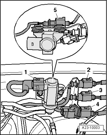 Note
Note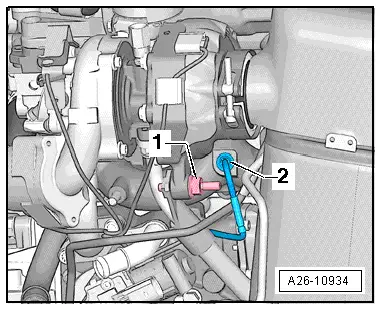
 Note
Note
Note
Note