audi Workshop Repair Guides

Audi Workshop Service and Repair Manuals

Removing and installing intermediate shaft > < Removing and installing drive shaft with intermediate shaft (version with splines on inner joint)
Removing and installing drive shaft (version with internal splines on inner sliding CV joint)
   
Removing and installing drive shaft (version with internal splines on inner sliding CV joint)
Special tools and workshop equipment required
t  Multi-purpose tool -VW 771-
t  Tensioning strap -T10038-
t  Drive shaft puller -T10382-
t  Torque wrench -V.A.G 1332-
t  Angle wrench -V.A.G 1756-

Removing
–  Loosen bolt securing drive shaft at wheel hub.
Procedure for loosening bolt securing drive shaft at wheel hub:
t  → Chapter „Loosening and tightening hexagon bolt securing drive shaft“.
t  → Chapter „Loosening and tightening twelve-point ribbed bolt securing drive shaft“.
t  → Chapter „Loosening and tightening twelve-point bolt (without ribbing) securing drive shaft“
–  Remove wheel.
–  Remove noise insulation → Rep. gr.66.
–  To remove drive shaft on left side, first remove bottom section of wheel housing liner → Rep. gr.66.
–  If fitted, remove vehicle level senders → Chapter.
   
–  Mark positions of nuts -arrows- with felt pen.
–  Unscrew nuts -arrows-.
–  Guide wishbone out of wheel bearing housing together with swivel joint.
–  Detach coupling rod from anti-roll bar on both sides.
–  Slide outer joint by hand out of wheel hub.
–  Secure drive shaft to prevent it from dropping.
  Note
The suspension strut with all the attached components must be pulled towards the rear in order to extract the drive shaft from the gearbox using drive shaft puller -T10382-. When doing this, take care not to damage any other parts (such as the brake hose or ABS wiring).
  A40-10111
–  Pull suspension strut with attached components towards the rear using tensioning strap -T10038- (e.g. secured to arm of lifting platform) until drive shaft puller -T10382- can be inserted parallel with drive shaft.
  N40-10284
Set up drive shaft puller -T10382-.
For the sliding constant velocity joint -1- the recess -arrow- on the puller plate -T10382/1- must face the spindles -T10382/2-.
  N40-10297
–  Apply puller plate -T10382/1- behind sliding constant velocity joint -1-.
The recess -arrow- on puller plate -T10382/1- must face towards sliding constant velocity joint -1-.
  N40-10333
–  Attach spindles -T10382/2- and cross piece -T10382/3- to puller plate -T10382/1-.
–  Attach multi-purpose tool -VW 771- to cross piece -T10382/3-.
  N40-10334
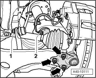
–  Pull out drive shaft by striking multi-purpose tool -VW 771- as required.
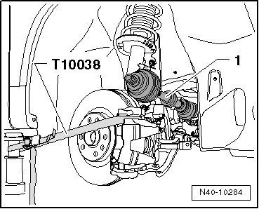
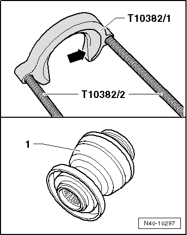
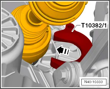
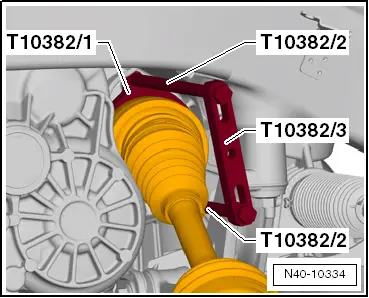
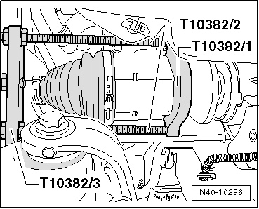
  Note
When removing drive shaft on right side, ensure sufficient clearance from heat shield; re-position drive shaft puller -T10382- as necessary.
–  Take drive shaft out of vehicle.
Installing
Installation is performed in reverse sequence; note the following:
Tightening torques → Chapter „Exploded view of wheel bearing housing and wheel bearing unit“
Tightening torques → Chapter „Exploded view of subframe, diagonal strut, swivel joint, anti-roll bar, wishbone, suspension bracket and vehicle level senders“
Four-wheel drive vehicles
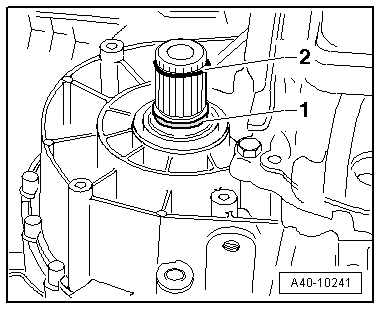
–  Strike end of stub shaft (right-side) using a plastic hammer.
  Caution
l  This ensures that the circlip on the stub shaft engages correctly in the differential pinion.
l  It will also help to prevent leakage.
Applies to all vehicles:
–  Before fitting the outer joint in the wheel hub, apply a thin coat of assembly paste to the splines on the outer joint → Electronic parts catalogue.
Remove any paint residue and/or corrosion on thread and splines of outer joint.
  N40-10296
–  Fit new seal -1- and circlip -2- in groove of stub shaft on gearbox.
–  Apply approx. 2 g of grease all round splines on end of gearbox shaft → Electronic parts catalogue.
–  Mesh outer and inner splines of gearbox shaft and sliding constant velocity joint.
–  Take hold of drive shaft and slide it into constant velocity joint as far as it will go.
–  Then push constant velocity joint onto stub shaft on gearbox with a sudden, hard push.
  Note
t  If the drive shaft cannot be pushed in easily, even though the splines are aligned correctly, you can make use of the sliding travel in the constant velocity joint.
t  DO NOT use a hammer or the like.
–  Check the firm fit of the sliding constant velocity joint by pulling the joint against the resistance of the circlip.
  Caution
For this check, pull only on the sliding constant velocity joint and NOT on the drive shaft.
–  Detach tensioning strap -T10038-.
–  Guide outer joint into wheel hub splines as far as possible.
  A40-10241
–  Align position of nuts -arrows- according to markings made on removal and tighten nuts.
  Note
Ensure sealing boot is not damaged or twisted.
–  Attach noise insulation (bottom) → Rep. gr.66.
–  After installing drive shaft on left side, re-install bottom section of wheel housing liner → Rep. gr.66.
–  If fitted, install vehicle level senders → Chapter.
–  Tighten bolt securing drive shaft to wheel hub.
Procedure for tightening bolt securing drive shaft to wheel hub:
t  Tighten hexagon bolt securing drive shaft → Chapter.
t  Tighten twelve-point ribbed bolt securing drive shaft → Chapter.
t  Tighten twelve-point bolt (without ribbing) securing drive shaft → Chapter.
–  On vehicles with electronic damping control (Audi magnetic ride), re-adapt reference position → Vehicle diagnostic tester.
–  On vehicles with automatic headlight range control, carry out basic adjustment of headlights → Rep. gr.94.
  A40-10111

Removing and installing intermediate shaft > < Removing and installing drive shaft with intermediate shaft (version with splines on inner joint)