
A4 Cabriolet Mk2
| Removing engine - vehicles with automatic gearbox |

| Special tools and workshop equipment required |
| t | Used oil collection and extraction unit -V.A.G 1782- |
| t | Hose clip pliers -V.A.G 1921- |
| t | Spark plug connector pliers -V.A.G 1922- |
| t | Stepladder -VAS 5085- |
| t | Scissor-type assembly platform -VAS 6131 A- with support set for Audi -VAS 6131/10- |
| t | Drip tray for workshop hoist -VAS 6208- |
 Note
Note
|
|
|
|
|
Note
|
|
 Caution
|
|
 WARNING
|
|
|
|
|
|
|
|
|
|
|
|
Note |
|
|
|
|
|
|
|
|
|
|
|
|
|
|
|
|
|
Note |
|
|
|
|
|
|
|
Note
|
|
|
|
|

|
|
|
|
|
|
|
|
|
|
|
|
|
|
|
Note |
|
Note
|
|
|
|
|
|
|
|
|
|
Note
|
|
|
|
|
|
|
|
|
|
|
|
Note
|
|
|
|
|
|
Note
|
|
|
|
|

|
|
|
|
|
|
|
|
|
Note |
|
Note
|
|
|
|
|
|
|
|
|
|
|
|
|
|
|
|
|
|
|
|
|
|
|
|
Note |
|
|
|
Note |

|
Note
|
|
|
|
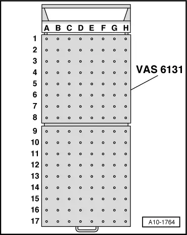
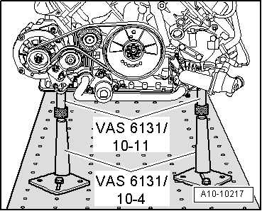
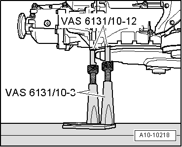
| Platform coordinates | Parts of support set for Audi -VAS 6131/10- | |||
| B4 | /10-1 | /10-4 | /10-5 | /10-11 |
| G3 | /10-1 | /10-4 | /10-5 | /10-11 |
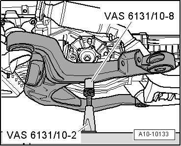
| B10 | /10-1 | /10-2 | /10-5 | /10-8 |
| G10 | /10-1 | /10-2 | /10-5 | /10-8 |
| C15 | /10-1 | /10-3 | /10-5 | /10-12 |
| F15 | /10-1 | /10-3 | /10-5 | /10-12 |
|
|
|
|
|
|
|
|
|
|
|
Note
|
|