
A4 Cabriolet Mk2
|
 Note
Note
|
|
|
|
|
|
|
|
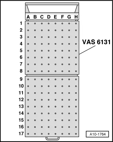
| Platform coordinates | Parts of support set for Audi -VAS 6131/10-, -VAS 6131/11- and -VAS 6131/12- | |||
| B4 → Note | /10-1 | /10-4 | /10-5 | /10-11 |
| G3 → Note | /10-1 | /10-4 | /10-5 | /10-11 |
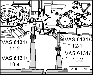
| B7 | /10-1 | /10-4 | /10-5 | /11-2 |
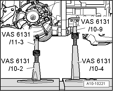
| G7 | /10-1 | /10-4 | /10-5 | /10-9 |
| B10 | /10-1 | /10-2 | /10-5 | /12-1 |
| G10 | /10-1 | /10-2 | /10-5 | /11-3 |
| C15 → Note | /10-1 | /10-3 | /10-5 | /10-12 |
| F15 → Note | /10-1 | /10-3 | /10-5 | /10-12 |
|
|
|
|
|
Note
|
|
|
|
|
|
Note
|
|
|
|
Note |
|
|
|
|
|
|
|
|
|
|
|
|
|
Note
|
|
|
|
|
|
Note
|
|
|
|
|
|
|
|