|
Servicing shift mechanism
Dismantling and assembling shift mechanism with Tiptronic (assembly overview)
Dismantling
-
‒ Removing shift mechanism .
-
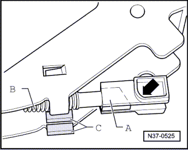
‒ First detach buffer stop from cable lever.
-
‒ Set the selector lever to Tiptronic and then remove the frame.
-
‒ Shift selector lever into position "2".
-
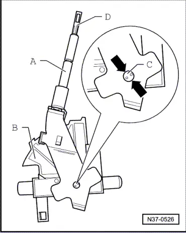
‒ Disengage lever for interlock cable by lifting it out of its mounting and remove from the bearing cup.
-
‒ Shift selector lever into position "D".
-
‒ Carefully select the detent spring for the Tiptronic setting out of the bearing cup, working from the outside.
-
‒ Withdraw the locks for the selector lever bearing bushes.
-
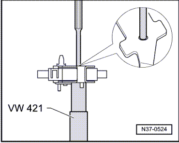
‒ Use a screwdriver to push the selector lever bearing bushes out.
-
‒ Remove the complete selector lever.
-
‒ Dismantling selector lever => Page 37-35.
-
‒ To remove the bearing for the selector lever Tiptronic setting release the retaining lugs on the outside of the bearing cup and remove the bearing towards the inside.
-
‒ Press out the pin for the locking pawl using a punch.
-
‒ Lift out the selector lever lock solenoid together with the locking pawl.
-
‒ Carefully lever the detent spring for the selector lever settings out of the bearing cup working from the outside.
-
‒ Lever out both pivot pins of the cable lever/retainer.
-
‒ Pull the cable lever/retainer out of the bearing cup with the opening of the retainer facing upwards.
-
‒ Unclip the retainer from the cable lever.
Assembling
-
‒ Clip the retainer into the cable lever.
-
‒ Push the cable lever/retainer from above into the bearing cup with the retainer opening first.
-
‒ Drive the two pivot pins of the cable lever/retainer from both sides into the bearing cup right to the limit.
-
‒ Press the detent spring with roller for the selector lever setting fully into its mounting in the bearing cup.
-
‒ Push the selector lever lock solenoid into the bearing cup from above together with the locking pawl.
-
‒ Drive the pin for the locking pawl in carefully.
-
‒ Check the engagement of the locking pawl in "P" and "N" on the selector lever mechanically using a screwdriver.
-
‒ Insert the complete selector lever in the bearing cup.
-
‒ Attach the selector lever at the bottom and the top in the cable lever.
-
‒ Push the two bearing bushes for the selector lever into the bearing cup from the front and rear respectively.
-
‒ Fit the locks for the bearing bushes in the bearing cup so their angled ends face inwards.
-
‒ Press the detent spring for the Tiptronic setting fully into its mounting in the bearing cup.
-
‒ Shift selector lever into position "2".
-
‒ Place the locking lever in the bearing cup and engage it firmly until it is felt to lock into place in both bearings.
-
‒ Check the locking function of the locking lever. When the selector lever is set to "P" it must engage in the retainer and block gear shifting.
-
‒ Mount the frame on the bearing cup (with the ribs pointing upwards) and insert the buffer stop in the cable lever.
-
‒ Installing shift mechanism => Page 37-6.
Dismantling and assembling the selector lever
-
‒ Removing the selector lever => from Page 37-31.
|