audi Workshop Repair Guides

Audi Workshop Service and Repair Manuals

Removing and installing selector lever cable at shift mechanism without Tiptronic > < Removing and installing locking cable at shift mechanism with Tiptronic
Automatic Gearbox 01VFWD and 4WD
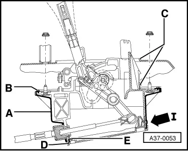
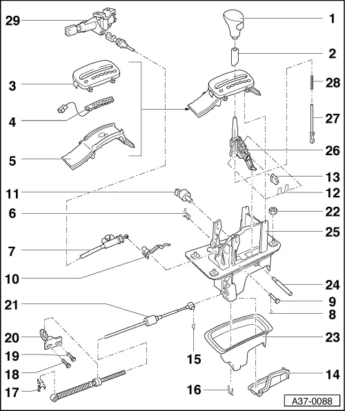
Servicing shift mechanism
Dismantling and assembling shift mechanism without Tiptronic
 
A37-0088

The shift mechanism with Tiptronic is described from Page => 37-6 onwards.

  • Handle for selector lever
    • ◆ Push the sleeve 2 downwards, pull the button in the handle out as far as it will go, and then remove the handle by pulling it upwards.
  • Sleeve
    • ◆ Engages in selector lever handle

Note:

Before any further service work can be performed on the shift mechanism, the front section of the centre console must first be removed.

=> General Body Assembly, Interior; Repair group 68; Shelves and trays/covers; Removing and installing front part of centre console

 
A37-0088
  • Cover
    • ◆ With gear indicator and indicator for selector lever lock
    • ◆ To remove, disengage the retainer lugs from the mount
    • ◆ To remove, lift upwards together with Item 4 and Item 5.
  • Light strip
    • ◆ With wiring and light emitting diodes (LED) for basic illumination
    • ◆ Cable layout => Fig.37-60
  • Guide
    • ◆ With masking panel and mirror for individual gear indication
    • ◆ Removal can be released by releasing the four securing lugs on inner side of cover.
 
A37-0088
  • Securing spring
    • ◆ For locking cable
    • ◆ Clip into bearing cup
  • Locking cable
    • ◆ Must not be kinked
    • ◆ Removing => Page 37-46
    • ◆ Installing and adjusting => Page 37-68
  • Lock washer
    • ◆ For bolt, -9-
  • Pin
    • ◆ For lever, -10-
 
A37-0088
  • Lever for locking cable
  • Solenoid for selector lever lock -N110
    • ◆ Removing and installing => Fig.37-60
    • ◆ Unclip connector from wiring harness (at centre console) => Fig.37-60
    • ◆ Can be checked in electrical test and in measured value block

=> Repair group 01; Performing self-diagnosis; Read measured value block

  • Spring clip
    • ◆ Insert both ends into selector lever
  • Latch
    • ◆ Insert together with spring clip in selector lever
 
A37-0088
  • Cover
    • ◆ For mounting bracket
    • ◆ Removing and installing => Fig.37-58
  • Fixing
    • ◆ To secure the gate selector cable to the selector lever
  • Locking plate
    • ◆ For selector lever cable at bearing cup =>Fig.37-59 Item E
  • Clamp
    • ◆ For selector lever cable on selector lever on gearbox
  • Hexagon bolt - 23 Nm
  • Hexagon bolt - 23 Nm
  • Support bracket
    • ◆ For gate selector cable at the gearbox
 
A37-0088
  • Selector lever cable
    • ◆ Removing and installing
    • ◆ Adjusting => Page37-44

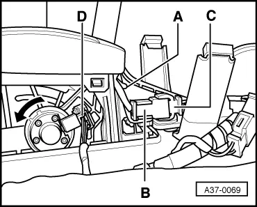
Note:

Before any further service work can be performed on the shift mechanism, the shift mechanism must be completely removed from the vehicle.

  • Nut- 9 Nm
    • ◆ 4 pieces
  • Rubber housing
    • ◆ Must only be separated from mounting bracket -25 if damaged and when dismantling selector lever
    • ◆ Assembly and installation position => Fig.37-59
 
A37-0088
  • Pivot pin
    • ◆ Removal: Carefully lever out with a screwdriver
  • Mount
    • ◆ Removing and installing => Fig.37-59
  • Gate lever
  • Pull rod
    • ◆ Insert into the selector lever together with the spring, 28
  • Spring
    • ◆ For pull-rod
  • Ignition/starter switch
 
A37-0053

→ Fig.1    Removing and installing cover

Note:

The cover can be removed and installed from below with shift mechanism installed

Removal

  • ‒ Press into direction of -arrow I- and release snap fastener for bearing cup.

Installing

  • ‒ Guide cover into groove -D- and then engage the snap fastener.
  • ‒ Ensure the cover seats and seals perfectly.
 
A37-0053

→ Fig.2    Removing and installing bearing cup

  • ‒ Remove lower protective plate and catalytic converter.
  • ‒ Detach selector lever cable from bearing cup:
  • ‒ Before installing secure rubber housing -A- on bearing cup.
  • ‒ Tighten nut to 9 Nm

Note:

  • ◆ The rubber housing -A- has to seal off bearing cup towards body (sealing lip -B-).
  • ◆ No cables should be installed between the body and mounting bracket
 
A37-0069

→ Fig.3    Removing and installing solenoid for selector lever lock -N110

  • ‒ Unclip connector -D- (wiring harness console).
  • ‒ Rotate solenoid in direction of arrow by approximately 90°.
  • ‒ When the lifting magnet has been renewed, check the gear shift mechanism

 
A37-0069

→ Fig.4    Routing wiring for basic illumination

  • ‒ Route cable for basic illumination under guide and fix into notch -A- (left/right).
  • ‒ Clip connector -B- into retainer on guide.
  • ‒ Clip in connector of wiring harness (console).

Removing and installing selector lever cable at shift mechanism without Tiptronic > < Removing and installing locking cable at shift mechanism with Tiptronic