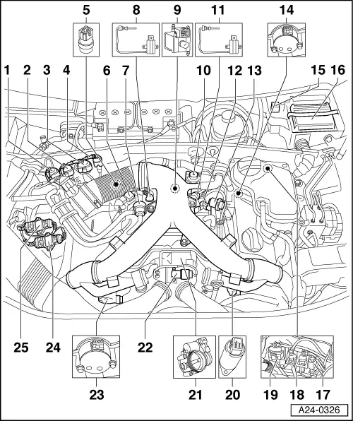
Connector for Bank 1 Lambda probe 2 -G130 and Lambda probe heater -Z29
◆ 4-pin/green
Connector for Bank 2 Lambda probe 2 -G131 and Lambda probe heater -Z30
◆ 4-pin/brown
Connector for Bank 1 Lambda probe 1 -G39 and Lambda probe heater -Z19
◆ 4-pin/black
3 pin connector
◆ For knock sensor 1 (G61)
Coolant temperature sender (G62)
◆ On coolant pipe behind cylinder head, Bank 1
Charge pressure control solenoid valve (N75)
Activated charcoal filter solenoid valve 1 (N80)
Exhaust gas temperature sender 1 (G235)
◆ At rear of intake manifold on the left-hand side (looking from the front of the engine compartment). On vehicles meeting emission standard EU-III, the exhaust gas temperature sender 2 (G236) is located at this position as well, see Page 10-41.
Secondary air inlet valve -N112
◆ Not fitted on this engine version
Secondary air pump motor -V101
◆ Not fitted on this engine version
Exhaust gas temperature sender 2 (G236)
◆ On vehicles meeting emission standard EU III, this sender is fitted together with exhaust gas temperature sender -1- (G235) at position -8-. In that case both senders are fitted one behind the other, see Page 10-41.
Air recirculation valve for turbocharger (N249)
Fuel pressure regulator
Hall sender (G163)
◆ Cylinder bank 2
Relay for secondary air pump (J299)
◆ Not fitted on this engine version
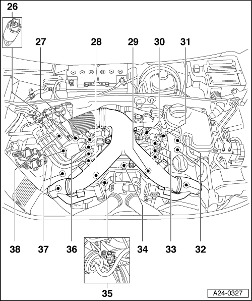
Engine control unit (J220)
3 pin connector
◆ For engine speed sender (G28)
◆ Grey
3 pin connector
◆ For knock sensor 2 (G66)
Connector for Bank 2 Lambda probe 1 -G108 and Lambda probe heater -Z28
◆ 4-pin/black
Camshaft adjustment valve 2 (N208)
Throttle valve control part (J338)
◆ With throttle valve drive (G186), angle sender for throttle valve drive (G187) and angle sender 2 for throttle valve drive (G188)
Charge pressure sender (G31)
◆ In rubber connecting piece in front of throttle valve control part
Hall sender (G40)
◆ Cylinder bank 1
Output stage 2 (N192)
◆ For ignition coils on cylinder bank 2
Output stage (N122)
◆ For ignition coils on cylinder bank 1
Camshaft adjustment valve 1 (N205)
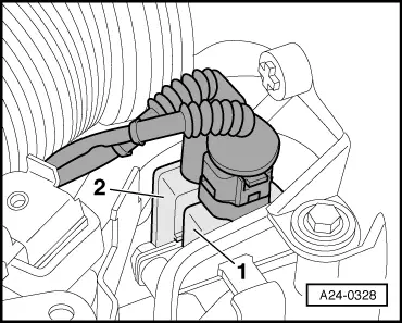
Bank 1 Lambda probe 1 -G39 with lambda probe heater -Z19
Knock sensor 1 (G61)
Knock sensor 2 (G66)
Engine speed sender (G28)
◆ In gearbox housing above sender disc
Bank 2 Lambda probe 1 -G108 with lambda probe heater -Z28