audi Workshop Repair Guides

Audi Workshop Service and Repair Manuals

Suspension strut and upper link > < Servicing subframe
Running gear, Front-wheel drive and four-wheel drive
Servicing rear axle (four-wheel drive vehicles)
Removing and installing rear axle

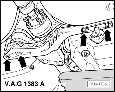
Special tools and workshop equipment required

  • ◆ V.A.G 1331 Torque wrench
  • ◆ V.A.G 1332 Torque wrench
  • ◆ V.A.G 1383 A Engine/gearbox lifter
  • ◆ V.A.G 1752/1 Spring tensioner
  • ◆ V.A.G 1752/3 Spring holder

Removing

 
V44-0408
  • ‒ Remove rear centre console.

=> General Body Repairs; Repair Group 70; Shelves/Trim, Removing and installing rear centre console

  • ‒ → Detach wheel trim. In the case of light alloy wheels, use puller from vehicle tool kit or suction grip -3208- to remove trim cap.
  • ‒ Unscrew both rear wheels.
  • ‒ Separate exhaust system at clamp and remove rear section of exhaust system.

=> Engine, Mechanics; Repair Group 26; Removing and installing exhaust system components

Note:

To avoid damage, decoupling element in front exhaust pipe is never to be kinked by more than 10 °.

  • ‒ Remove rear heat shield for propshaft.
  • ‒ If necessary, tie exhaust pipe with catalytic converter to propshaft centre bearing.
 
V39-1727
  • ‒ → Check for factory mark (coloured dot -arrows-) at propshaft and at flange/propshaft at rear final drive. If there is no coloured dot, make coloured mark to identify position of propshaft flange -A- with respect to rear final drive -B-.
 
A42-0141
  • ‒ Slacken off bolts of propshaft flange.
  • ‒ → Tie propshaft with wire to underside of vehicle -arrows-. Place wooden block -1- beneath propshaft.
  • ‒ Remove handbrake cables.

=> Brake System; Repair Group 46; Removing and installing handbrake cables

Note:

If same rear axle is to be re-installed, only disengage handbrake cables at handbrake lever, on underside of vehicle and at fuel tank. In this case, handbrake cables at rear axle and brake calipers are to be left engaged.

 
A42-0142
  • ‒ → Disconnect brake pipes at joints -1- and -2- on underside of vehicle at rear left.
  • ‒ Unclip brake pipes from holder -arrow- on underside of vehicle.
 
A42-0143
  • ‒ → Unscrew -1- and -2- holders of wires to rear right and rear left speed sensors -G44 and -G46 at lower link.
  • ‒ Pull rear right and rear left speed sensors -G44 and -G46 -arrow- out of wheel bearing housing.
  • ‒ Disengage wires to speed sensors at front of subframe.

 
A42-0144
  • ‒ → Apply spring tensioner V.A.G 1752/1 with spring holder V.A.G 1752/3 (with pads) at second and second last winding of coil spring.
  • ‒ Pre-tension coil spring.

Notes:

  • ◆ If applicable, pay attention to headlight range control .
  • ◆ Removal and installation of rear axle or lower link involves unfastening connecting link of rear left/rear right vehicle level sender -G76/ -G77 at lower link.
 
A42-0046
  • ‒ → Slacken off bolts -arrows- at adapter with coil spring still tensioned.
  • ‒ Swivel top of suspension strut outwards and slacken off coil spring.

Notes:

  • ◆ Take care not to damage edge of wheel housing.
  • ◆ Unscrew opposite suspension strut from wheel housing in same manner.
  • ‒ Unscrew bracket for exhaust system from final drive.
 
A42-0145
  • ‒ → Support final drive with engine/gearbox lifter V.A.G 1383 A.
  • ‒ Secure final drive with strap.

Note:

Take care not to damage fuel tank.

 
V39-1735
  • ‒ → Screw out bolts -arrows- at front cross member for rear final drive.

 
A42-0146
  • ‒ → Slacken off 4 bolts -arrows- of subframe.
  • ‒ Slowly lower subframe with final drive.

Note:

Take care not to damage edge of wheel housing.

Installing

Install in reverse order, paying attention to the following:

Remove any paint remnants, adhesive remnants and or/corrosion in thread/splines.

Notes:

 
V39-1727
  • ◆ → To prevent imbalance, flanges of propshaft -A- and rear final drive -B- must be fitted such that coloured marks are aligned -arrows-.
  • ◆ Replace seal between propshaft and input flange (remove backing and bond seal to flange shaft). Bonding surface must be free from grease.
  • ◆ Replace propshaft bolts (self-locking).
  • ‒ Bleed brake system.

=> Brake System; Repair Group 46; Bleeding brake system

  • ‒ Adjust handbrake.

=> Brake System; Repair Group 46; Removing and installing handbrake lever

  • ‒ Perform stress-free alignment of exhaust system.

=> Engine, Mechanics; Repair Group 26; Removing and installing exhaust system components

  • ‒ Replace the 4 subframe bolts and corresponding washers.
  • ‒ Pay attention to installation position of washers: Ribbed side faces upwards
  • ‒ Attach connecting link of rear left/rear right vehicle level sender -G76/ -G77 to lower link .
  • ‒ Fit and secure wheels .
  • ‒ Perform wheel alignment => Page 44-13.

Tightening torques

Component

Nm

Subframe to body

110 + 90°1)2)

Adapter for suspension strut to body

55

Propshaft to final drive (input flange) M8

55

Front cross member for rear final drive to body M10


40

Front cross member for rear final drive with exhaust system bracket to body M8


20

Drive shaft to rear final drive M10

80

Connecting link of rear left/rear right vehicle level sender -G76/ -G77 to lower link


103)

    1)    Replace bolt

    2)    90°corresponds to quarter turn

    3)    Replace nut

Suspension strut and upper link > < Servicing subframe