audi Workshop Repair Guides

Audi Workshop Service and Repair Manuals

Removing and installing gearbox support (left and right) > < Removing
Installing gearbox
Installing gearbox
  Note
t  Clean ATF pipes and ATF cooler before installing a replacement gearbox → Chapter.
t  Renew self-locking nuts and bolts when performing assembly work.
t  Renew oil seals and gaskets, and bolts which are tightened by turning through a specified angle.
t  Renew bolts securing torque converter to drive plate. Use only genuine bolts → Electronic parts catalogue.
t  It is important to clean the threads in the flange shafts on the gearbox and rear final drive to remove any remaining locking fluid after removing the propshaft. Otherwise there is a danger that the new bolts will seize when they are screwed in and then shear off the next time they are removed.
t  The threads can be cleaned with a thread tap.
t  Secure all hose connections with the correct hose clips (as original equipment); refer to → Electronic parts catalogue.
t  All cable ties which are released or cut open during removal must be fitted in the same position when installing.
t  If the dowel sleeves get stuck in the gearbox housing they must be removed and new dowel sleeves must be fitted on the cylinder block.
   
Vehicles with 1.8 ltr. turbocharged petrol engine:
A - Dowel sleeves
  A37-0075
All vehicles with 6-cylinder engine:
A - Dowel sleeves
  A37-0361
Vehicles with 2.5 ltr. TDI engine:
–  Before installing gearbox, check that brace -B- is still moved to one side -direction of arrow-. (The brace will be pivoted back down after the gearbox has been installed.)
Continued for all vehicles:
–  If fitted, re-install intermediate plate between engine and gearbox in the original position.
  A34-0116
–  Set up gearbox support -3282- with adjustment plate -3282/19- to support automatic gearbox 01V and place on engine and gearbox jack -V.A.G 1383 A-.
  Note
The symbols on the adjustment plate indicate the required supports for the automatic gearbox 01V (the arrow points in the direction of travel).
–  Place gearbox on engine and gearbox jack -V.A.G 1383 A-.
  A37-0064
–  Secure gearbox to gearbox support -3282- with bolt -A-.
  N37-0426
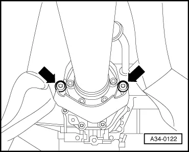
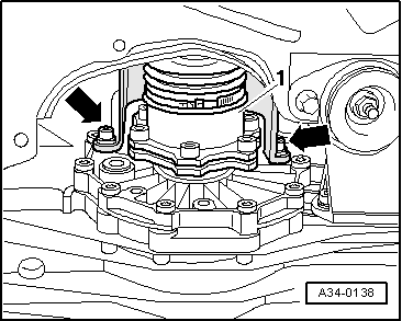
–  Before installing the gearbox ensure that the torque converter has been correctly fitted in the gearbox → Chapter.
l  
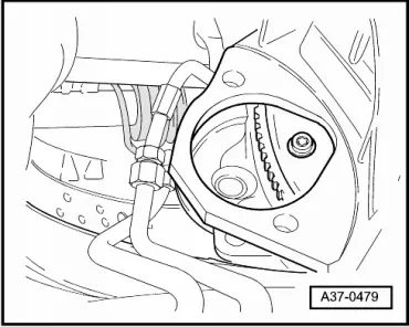
If the torque converter is correctly installed, the depth between the contact surfaces at the tapped holes on the torque converter and the contact surface of the torque converter bellhousing will be approx. 23 mm.
l  If the torque converter has not been fully inserted, the distance will be only approx. 11 mm.
  Caution
If the torque converter is not fitted correctly, the drive lugs on the torque converter or the ATF pump will be irreparably damaged when the gearbox is joined to the engine.
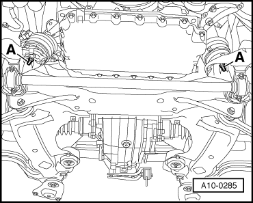
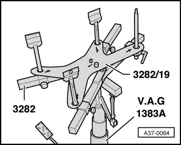
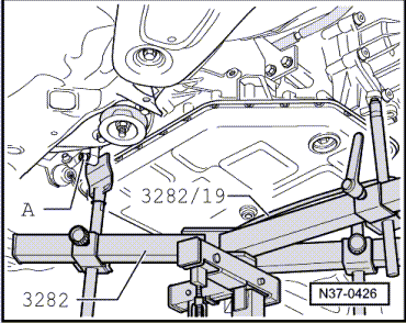
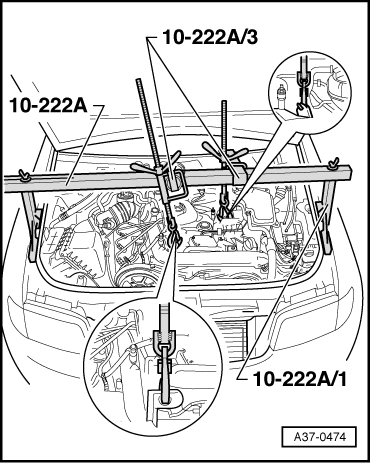
–  Guide in gearbox between lowered subframe and underbody.
–  Align gearbox with engine.
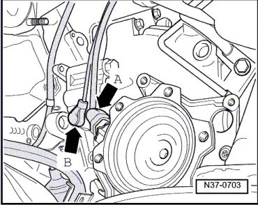
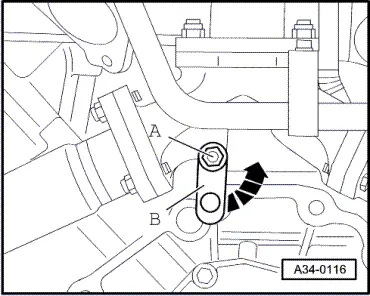
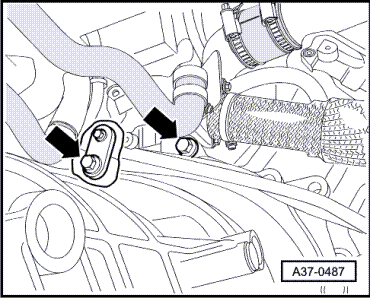
–  Before joining engine and gearbox, turn torque converter and drive plate (on engine) until one hole and one tapped hole are in line with the opening for the removed starter.
  Note
Make sure that no wiring or pipes are trapped when bringing engine and gearbox together.
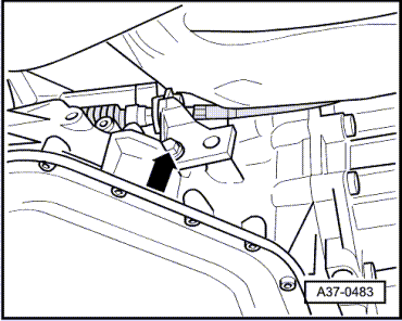
–  Install one engine/gearbox securing bolt on each side and tighten hand-tight.
  V32-0069
–  Use new bolts to secure torque converter to drive plate. Use only the correct bolts (same as original equipment) → Electronic parts catalogue.
–  Screw in 3 bolts -arrow- for torque converter through opening for removed starter. Tighten lightly to start with, and then tighten to specified torque (turning crankshaft 1/3 turn each time).
  Caution
Before and while you are tightening the bolts on the engine/gearbox flange keep checking that the torque converter can still be rotated behind the drive plate. If the converter cannot be turned, it must be assumed that it has not been installed correctly and the drive lugs on the converter or the ATF pump will be damaged when the bolts are fully tightened.
  A37-0479
–  Install top engine/gearbox securing bolts -arrows- and tighten to specified torque.
  Note
Some of these bolts are also used to secure a bracket or an earth connection → Anchor.
–  Install remaining engine/gearbox securing bolts and tighten to specified torque.
  A37-0487
–  Turn spindles approx. 8 turns to raise engine/gearbox assembly.
–  When raising engine/gearbox assembly, turn spindles alternately approx. 2 turns at a time.
–  At the same time raise engine/gearbox assembly using engine and gearbox jack -V.A.G 1383 A- (2nd mechanic required).
  A37-0474
If measurement performed with locating pin -3393- during removal showed that holes -1- and -2- were aligned:
–  Install subframe, observing tightening sequence → Rep. Gr.40.
If measurement performed with locating pin -3393- during removal showed that holes -1- and -2- were NOT aligned:
–  Only tighten bolts for subframe to torque setting, do not yet turn further (wait until wheel alignment has been carried out).
  WARNING
The vehicle must not be driven in this condition.
  A40-0125
–  Install engine mountings (left and right) → Rep. Gr.10.
–  Install gearbox supports (left and right) with gearbox mountings → Chapter.
  A10-0285
–  Unscrew bolt -A- and remove engine and gearbox jack -V.A.G 1383 A- with gearbox support -3282- and adjustment plate -3282/19-.
–  Apply anti-corrosion agent to point of contact between bolt -A- and oil pan.
  N37-0426
–  Push selector shaft lever -2- on gearbox forwards as far as it will go (in opposite direction to -arrow-).
–  Shift selector lever to “S” and carefully press ball head of selector lever cable -1- onto selector shaft lever, using pliers or similar.
  Note
Make sure you do not bend the selector shaft lever when pressing on the cable, as this would make it impossible to obtain an accurate adjustment of the selector mechanism.
  A37-0066
–  Bolt mounting bracket -arrow- for selector lever cable onto gearbox housing according to markings made earlier.
–  Install multifunction switch -F125- → Chapter.
–  Bolt propshaft onto gearbox → Rear final drive 01R; Rep. Gr.39 or → Rear final drive 08V; Rep. Gr.39.
  A37-0483
–  Install heat shield for propshaft -arrows-.
  A34-0122
–  Connect ATF pipes -1- according to paint markings.
  Note
The front end must be bolted to both longitudinal members when connecting the ATF pipes.
  N37-0699
–  Secure bracket -arrow- for ATF pipes to engine oil sump.
  A37-0480
–  Install bracket for noise insulation -1-.
–  Attach electrical connector -2- for multifunction switch -F125-.
–  Attach multi-pin connector for gearbox wiring harness and turn locking lever -3-.
–  Renew cable tie -4-.
–  Install heat shield for selector lever cable → Fig..
–  Install exhaust system and perform stress-free alignment → Rep. Gr.26.
  A37-0478
–  Install heat shield -arrows-.
  A37-0482
–  Attach electrical connector for speedometer sender -G22--arrow A-.
–  Install engine speed sender -G28--arrow B-.
  N37-0703
–  Secure both drive shafts to flange shafts (left-side drive shaft -1- shown in illustration) → Rep. Gr.40.
–  Install heat shields for drive shafts (left and right) -arrows-.
The remaining installation steps are carried out in the reverse sequence; note the following points:
–  Install noise insulation → Rep. Gr.66.
–  Follow the steps required after connecting the battery → Rep. Gr.27.
–  Check adjustment of selector lever cable → Chapter.
–  Fit front wheels and check and adjust wheel alignment as required → Rep. Gr.44.
–  Check and top up ATF level in planetary gearbox → Chapter.
–  Check oil level in front final drive → Chapter.
Tightening torques
  Note
t  Tightening torques apply only to lightly greased, oiled, phosphated or black-finished nuts and bolts.
t  Additional lubricant such as engine oil or gear oil may be used, but do not use graphite lubricant.
t  Do not use parts which have been degreased.
t  Tolerance for tightening torques ±15 %.
  A34-0138
ComponentNm
Bolts/nutsM610
 M820
 M1045
 M1265
Except for the following: 
Drive plate to torque converterM10x185 1)2)
Heat shields for drive shaft to gearbox23
Bracket for noise insulation to subframe10
l  1) Renew bolts.
l  2) Use only genuine bolts → Electronic parts catalogue.

   
1.8 ltr. turbocharged petrol engine to gearbox
  A37-0075
ItemBoltNm
1 … 4, 11M12x6765
5, 6M12x9065
7 … 10M10x4545
ADowel sleeves for centralising

   
3.0 ltr. petrol engine to gearbox
  A37-0361
ItemBoltNm
1, 8M12x6765
2M12x9065
3M12x7565
4 1)M10x6045
5M10x4545
6M10x8065
7 2)M12x11065
ADowel sleeves for centralising
l  1) With nut
l  2) With bracket for ATF pipes

   
2.5 ltr. TDI engine to gearbox
  A37-0361
ItemBoltNm
1 1)M12x8065
2 2)M12x9065
3M12x7565
4 3)M10x6045
5M10x4545
6M10x8065
7 4)M12x11065
8 4)M12x6765
ADowel sleeves for centralising
l  1) With bracket for turbocharger
l  2) With bracket for electrical wiring
l  3) With nut
l  2) With bracket for ATF pipes


Removing and installing gearbox support (left and right) > < Removing