
A4 Mk2
| Removing |
| Special tools and workshop equipment required |
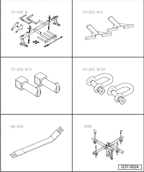
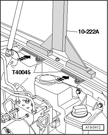
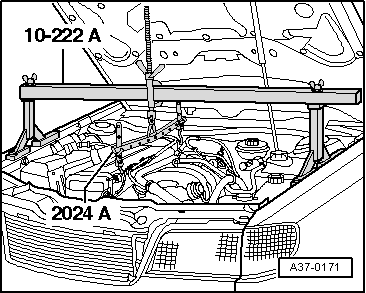
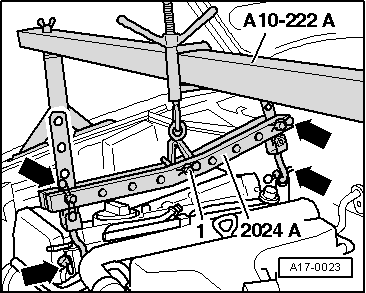
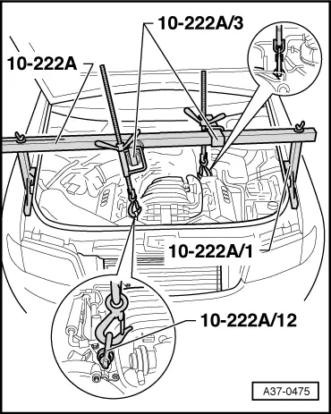
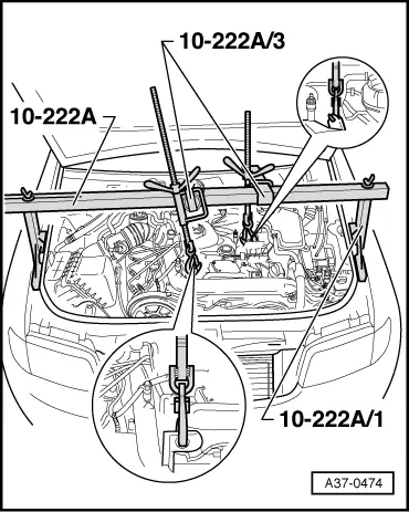
| t | Support bracket -10 - 222 A- |
| t | Rack -10 - 222 A/ 1- |
| t | Adapter -10 - 222 A /3- |
| t | Shackle -10 - 222 A /12- |
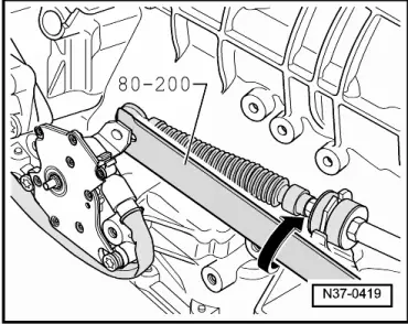
| t | Removal lever -80 - 200- |
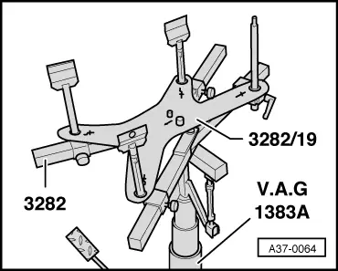
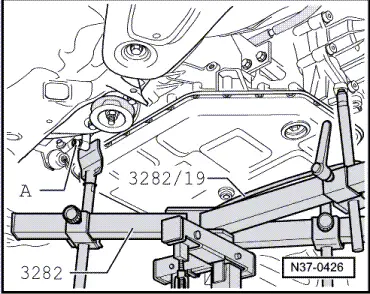
| t | Gearbox support -3282- |
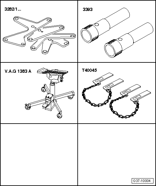
| t | Adjustment plate -3282/19- |
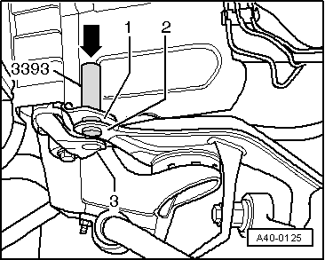
| t | Locating pins -3393- |
| t | Engine and gearbox jack -V.A.G 1383 A- |
| t | Wing compensation plate -T40045- |
|
|
|
|
|
|
|
|
|
|
 Note
Note
|
|
|
|
 Caution
|
|
|
|
|
|
|
|
|
|
|
|
|
|
|
|
|
|
|
|
|
|
Note
|
|
|
|
Note
|
|
|
|
|
|
Note
Note
|
|
|
|
|
|
|
|
|
|
|
|
|
|
|
|
|
|
Note
|
|
|
|
Note
|
|
|
|
Note
|
|
|
|
Note
|
|
|
|
|
|