
A4 Mk2
|
|
|
 Note
Note
Note
|
|
|
|
Note
|
|
|
|
Note
|
|
|
|
|
|
Note
|
|
|
|
|
|
|
|
| Example | ||||
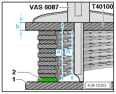
Mean value MD =
| 5.11 mm | |||
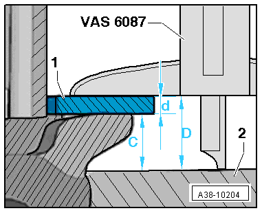
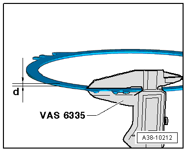
| - | Thickness -d- of outer plate -1- fitted | – 2.13 mm | ||
| = | Dimension -C- from sealing surface of input shaft to piston of reverse gear clutch | = 2.98 mm | ||
|
| Determination of shims for reverse gear clutch Clearance at least 3.0
| Determined and fixed measured values | |||||
| Measurement from sealing surface of input shaft to contact surface of corrugated washer in gearbox | Mean value MB | |||||
| Thickness of input shaft seal at gearbox housing | + | 0.27 mm | ||||
| Measurement from sealing surface of input shaft to piston of reverse gear clutch | - | Dimension “C” | ||||
| Measurement of compressed clutch assembly | - | Dimension “A” | ||||
| Minimum clearance | - | 3.0 mm | ||||
| Calculated thickness of both shims | = | “E” | ||||
|
Note
|
Note
|
|
 Caution
| Table 1 Determination of lower shim | Thickness “E1” of lower shim selected | ||
| “E” Measuring range in (mm) | Thickness (mm)
| ||
| 3,925 ... 4,174 | 2,15 | ||
| 4,175 ... 4,424 | 2,15 | ||
| 4,425 ... 4,674 | 2,65 | ||
| 4,675 ...4,924 | 2,9 | ||
| 4,925 ... 5,174 | 3,15 | ||
| 5,175 ...5,424 | 3,15 | ||
| 5,425 ... 5,674 | 2,65 | ||
| 5,675 ... 5,924 | 2,9 | ||
| 5,925 ... 6,174 | 3,15 | ||
| 6,175 ... 6,400 | 3,15 |
| Table 2 Determination of upper shim | Thickness “E2” of upper shim selected | ||
| Dimension “M2” = “E” - Selected lower shim “E1” Measuring range in (mm) | Thickness (mm)
| ||
| 1,829 ... 2,024 | 1,9 | ||
| 2,025 ... 2,324 | 2,15 | ||
| 2,725 ... 2,774 | 2,65 | ||
| 2,775 ... 3,024 | 2,9 | ||
| 3,025 ... 3,120 | 3,15 |
|
Note
|
|