
A4 Mk2
| Servicing drive shaft (with 100 mm dia. inner constant velocity joint) |
| Special tools and workshop equipment required |
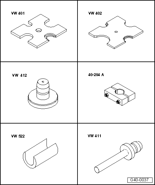
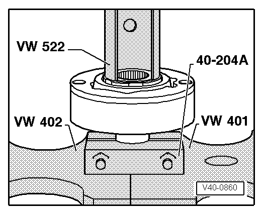
| t | Thrust plate -VW 401- |
| t | Thrust plate -VW 402- |
| t | Press tool -VW 412- |
| t | Tensioner -40-204 A- |
| t | Support sleeve -VW 522- |
| t | Press tool -VW 411- |
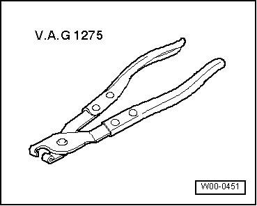
| t | Hose clip pliers -V.A.G 1275- |
|
|
| Grease quantity | of which in: | ||
| Outer joint | Total quantity | Joint | Boot |
| [mm] | [g] | [g] | [g] |
| 88 | 90 | 40 | 50 |
| Inner joint | Put in grease through ball bearing races | ||
| 100 | 80 | ||
|

| 1 - | Cover |
| q | Drive off carefully with drift → Fig. |
| q | Always renew |
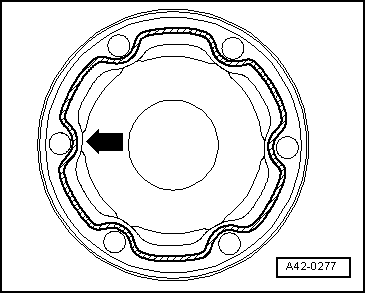
| q | Before fitting on constant velocity joint, coat sealing surface with D 454 300 A2 → Fig. |
| q | Align cover with bolt holes |
| 2 - | Circlip |
| q | Use normal commercial circlip pliers when removing and installing |
| q | Always renew |
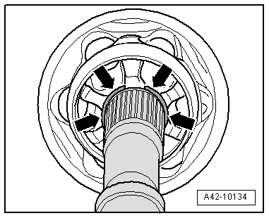
| 3 - | Inner constant velocity joint |
| q | Outside diameter: 100 mm |
| q | Renew only as complete unit |
| q | Pressing off → Fig. |
| q | Pressing on → Anchor |
| q | Greasing → Anchor |
| q | Adhesive surfaces must be free of oil and grease |
| q | Grease splines on drive shaft lightly with grease used in joint when fitting joint onto drive shaft |
| 4 - | Lock plate |
| 5 - | Multi-point socket head bolt |
| q | For correct version refer to → Parts catalogue |
| q | Tightening torques: |
| M 8 bolt: 40 Nm |
| M10 bolt: 65 Nm |
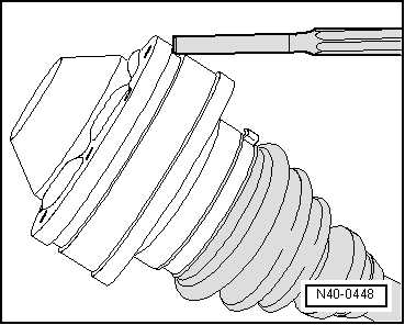
| 6 - | Boot with cap for inner constant velocity joint |
| q | With vent hole |
| q | Drive cap off carefully with drift |
| q | Always renew |
| q | Check inner constant velocity joint if boot is damaged → Chapter |
| q | Before fitting on constant velocity joint, coat sealing surface with D 454 300 A2 → Fig. |
| q | Align cover with bolt holes |
| q | Sealing surfaces (boot/drive shaft) must be free from grease when assembling |
| 7 - | Drive shaft |
| 8 - | Boot for outer constant velocity joint |
| q | Without vent hole |
| q | Check for splits and chafing, renew if necessary |
| q | Check outer constant velocity joint if boot is damaged → Chapter |
| q | Sealing surfaces (boot/drive shaft and boot/joint) must be free from grease when assembling |
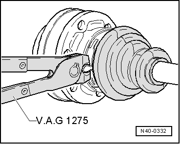
| 9 - | Hose clip |
| q | Always renew |
| q | Tightening → Fig. |
| 10 - | Circlip |
| q | Always renew |
| q | For correct version refer to → Parts catalogue |
| q | Insert in groove on shaft |
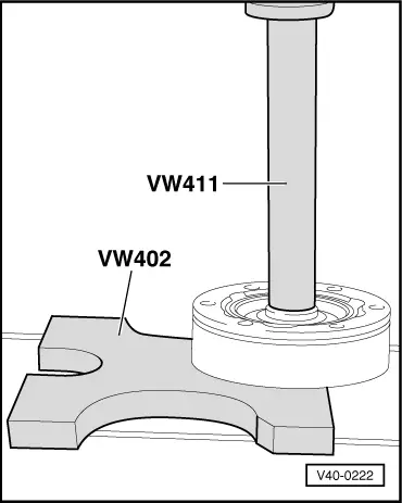
| 11 - | Outer constant velocity joint |
| q | Outside diameter: 88 mm |
| q | Renew only as complete unit |
| q | Driving off → Fig. |
| q | Installing: drive onto shaft with plastic hammer until compressed circlip seats |
| q | Circlip must fit in chamfer on joint when installing; guide with pliers if necessary |
| q | Greasing → Anchor |
| q | Grease splines on drive shaft lightly with grease used in joint when fitting joint onto drive shaft |
| 12 - | Flange bolt |
| q | Always renew |
| q | Tightening torque → Item |
|
|
|
|
|
|
|
|
 Note
Note
|
|
|
|
Note
|
|
|
|